Betonblokk szabványellenőrzése ausztrál szabványok szerint
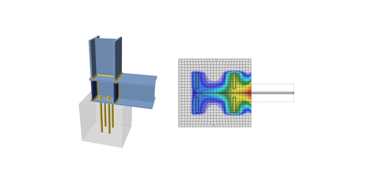
A talplemez alatti beton Winkler-féle altalajjal van szimulálva egyenletes merevséggel, amely a kontaktfeszültségeket biztosítja. A talplemezzel érintkezésben lévő terhelt területen az átlagos feszültséget használják a nyomási ellenőrzéshez.
Beton nyomási felület
A beton nyomási felületet az AS3600: 2018 – Cl. 12.6 szerint ellenőrzik. A beton felületen a méretezési nyomási feszültség nem haladhatja meg:
\[ ϕ f_b = ϕ 0.9 f'_c \sqrt{\frac{A_2}{A_1}} \le ϕ 1.8 f'_c \]
ahol:
- ϕ = 0,6 – kapacitástényező (2.2. táblázat), a Kódbeállításban szerkeszthető
- f'c – a beton jellemző nyomószilárdsága hengereken 28 napos korban
- A1 – nyomási terület
- A2 – a teherhordó felület legnagyobb területe, amely geometriailag hasonló és koncentrikus az A1-gyel. A csonkakúp oldalhajlása 1 hosszirányban és 2 keresztirányban a terhelés irányához képest.
A méretezési nyomási feszültség, σ, egyenlő a talplemez alatt, a betonnal érintkezésben lévő területen mért átlagos feszültséggel.
Nyíróerő átadása
A talplemezen ható nyíróerőt feltételezik, hogy az oszlopból az alapozás betonjába a következők útján adódik át:
- Súrlódás a talplemez és a beton / habarcs között
- Nyírófog
- Horgonycsavarok
Nyíróerő átadása súrlódással
A nyírási kapacitást Gianluca Ranzi, Peter Kneen: Design of Pinned Column Base Plates, Journal of the Australian Steel Institute, vol. 36, no. 2, September 2002 – 6.5.3. fejezet alapján számítják a következőképpen:
\[ ϕ V_f = ϕ μ N_c^* \]
ahol:
- ϕ = 0,8 – kapacitástényező
- μ = 0,55 – súrlódási együttható, a Kódbeállításban szerkeszthető
- Nc* – az oszlop méretezési tengelyirányú nyomóereje
Nyíróerő átadása nyírófog által
Ha a nyíróerőt a nyírófog adja át, a nyírófogat végeselem-módszerrel modellezik, és lemezei és hegesztései a végeselem-módszerrel és a hegesztési komponensekkel kerülnek ellenőrzésre. További ellenőrzések szükségesek – beton nyomási szilárdsága; beton élszilárdsága.
Beton nyomási szilárdsága
A beton nyomási szilárdságát Gianluca Ranzi, Peter Kneen: Design of Pinned Column Base Plates, Journal of the Australian Steel Institute, vol. 36, no. 2, September 2002 – 6.5.5. fejezet alapján ellenőrzik:
\[ ϕ_c V_b = 0.85 ϕ_c f'_c A_{sl} \]
ahol:
- ϕc = 0,6 – kapacitástényező a nyomásban lévő betonhoz, a Kódbeállításban szerkeszthető
- f'c – a beton jellemző nyomószilárdsága hengereken 28 napos korban
- Asl – a beágyazott nyírófog vetített területe az erő irányában, kivéve a betonszerkezet feletti habarccsal érintkező részt
Beton élszilárdsága
Ha nyíróerő hat egy szabad betonél ellen, ellenőrizni kell, hogy a beton képes-e felvenni az alkalmazott nyíróerő-hatást. A beton élszilárdságát Gianluca Ranzi, Peter Kneen: Design of Pinned Column Base Plates, Journal of the Australian Steel Institute, vol. 36, no. 2, September 2002 – 6.5.5. fejezet alapján ellenőrzik:
\[ ϕ V_{ce} = ϕ 0.33 \sqrt{f'_c} A_{Vc} \]
ahol:
- ϕ =0,85 – kapacitástényező
- f'c – a beton jellemző nyomószilárdsága hengereken 28 napos korban
- AVc – hatékony feszültségi terület, amelyet a nyírófog nyomási éleitől 45°-os síkot vetítve határoznak meg a szabad felület felé a nyíróterhelés irányában. A nyírófog nyomási területe ki van zárva a vetített területből
Nyíróerő átadása horgonyok által
A nyíróerőt feltételezik, hogy horgonyok adják át. Az egyes horgonyokban lévő erőt a végeselem-módszerrel határozzák meg. Minden egyes horgonyt vagy horgonycsoportot ellenőriznek acél tönkremenetelre nyírásban, beton éltönkremenetelre, beton kiszakadásos tönkremenetelre, valamint kombinált húzási és nyírási terhelésre, ha húzás is jelen van.