Finite element types
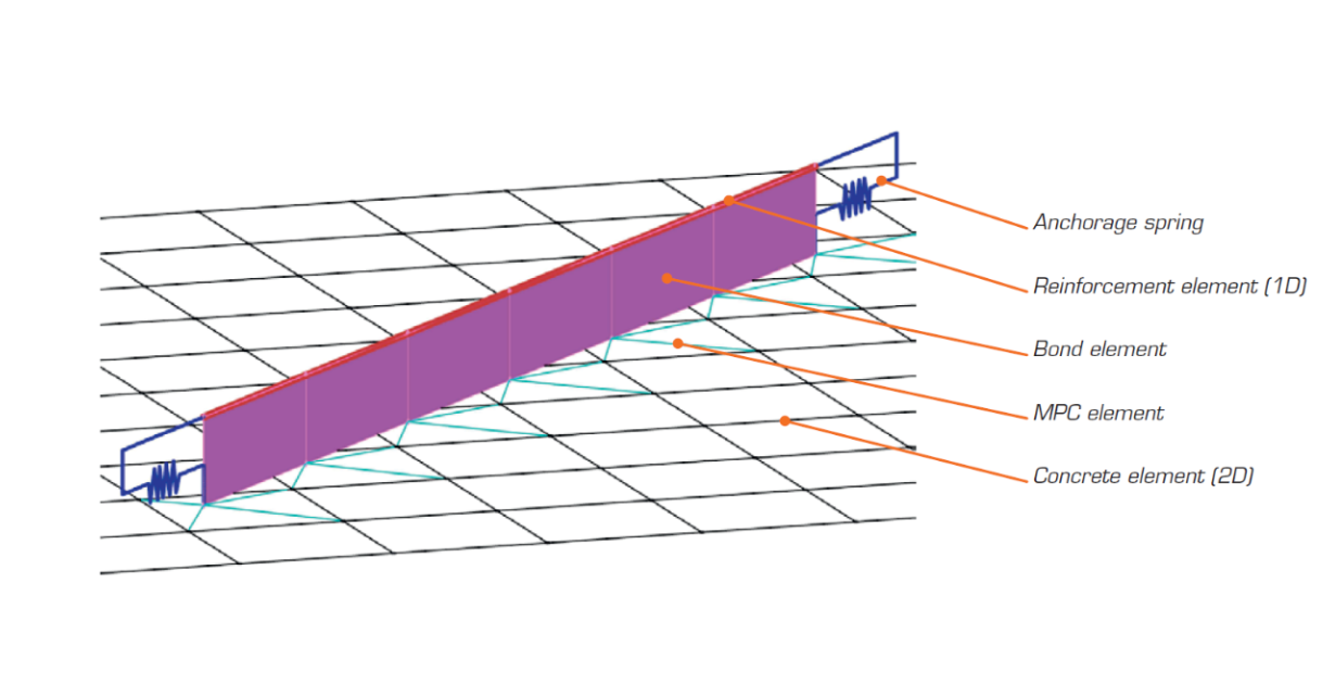
The non-linear finite element analysis model is created by several types of finite elements used to model concrete, reinforcement, and the bond between them. Concrete and reinforcement elements are first meshed independently and then connected to each other using multi-point constraints (MPC elements). This allows the reinforcement to occupy an arbitrary, relative position in relation to the concrete. If anchorage length verification is to be calculated, bond and anchorage end spring elements are inserted between the reinforcement and the MPC elements.
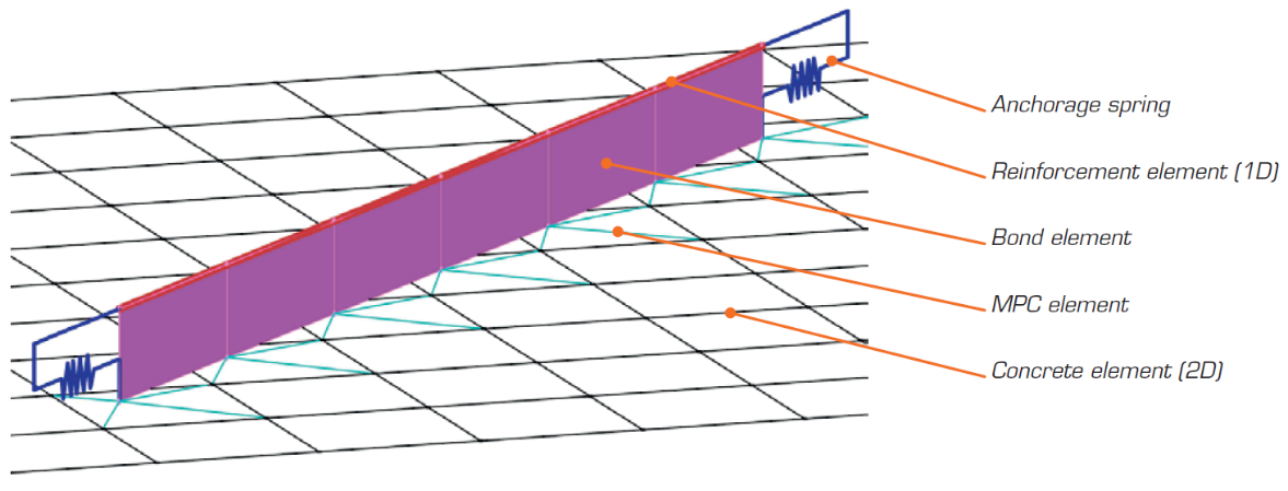
\[ \textsf{\textit{\footnotesize{Fig. 15\qquad Finite element model: reinforcement elements mapped to concrete mesh using MPC elements and bond elements.}}}\]
Concrete
Concrete is modeled using quadrilateral and trilateral shell elements, CQUAD4 and CTRIA3. These can be defined by four or three nodes, respectively. Only plane stress is assumed to exist in these elements, i.e., stresses or strains in the z-direction are not considered.
Each element has four or three integration points which are placed at approximately 1/4 of its size. At each integration point in every element, the directions of principal strains α1, α3 are calculated. In both of these directions, the principal stresses σc1, σc3 and stiffnesses E1, E2 are evaluated according to the specified concrete stress-strain diagram, as per Fig. 2. It should be noted that the impact of the compression softening effect couples the behavior of the main compressive direction to the actual state of the other principal direction.
Reinforcement
Rebars are modeled by two-node 1D “rod” elements (CROD), which only have axial stiffness. These elements are connected to special “bond” elements which were developed in order to model the slip behavior between a reinforcing bar and the surrounding concrete. These bond elements are subsequently connected by MPC (multi-point constraint) elements to the mesh representing the concrete. This approach allows the independent meshing of reinforcement and concrete, while their interconnection is ensured later.
Anchorage length verification: bond elements
The anchorage length is verified by implementing the bond shear stresses between concrete elements (2D) and reinforcing bar elements (1D) in the finite element model. To this end, a “bond” finite element type was developed.
The definition of the bond element is similar to that of a shell element (CQUAD4). It is also defined by 4 nodes, but in contrast to a shell, it only has a non-zero stiffness in shear between the two upper and two lower nodes. In the model, the upper nodes are connected to the elements representing reinforcement and the lower nodes to those representing concrete. The behavior of this element is described by the bond stress, τb, as a bilinear function of the slip between the upper and lower nodes, δu, see Fig. 16.
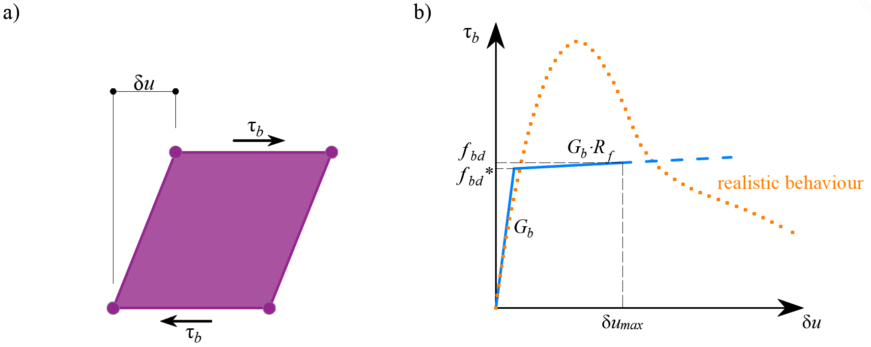
\[ \textsf{\textit{\footnotesize{Fig. 16\qquad (a) conceptual illustration of the deformation of a bond element; (b) a stress-deformation function.}}}\]
The elastic stiffness modulus of the bond-slip relationship, Gb, is defined as follows:
\[G_b = k_g \cdot \frac{E_c}{Ø}\]
where:
kg coefficient depending on the reinforcing bar surface (by default kg = 0.2),
Ec modulus of elasticity of concrete, taken as Ecm
Ø the diameter of the reinforcing bar.
The design values of ultimate bond shear stress, fbd, provided in the respective selected design codes EN 1992-1-1 (2015) or ACI 318-04 are used to verify the anchorage length. The hardening of the plastic branch is calculated by default as Gb/105.
Anchorage length verification: spring elements
The provision of anchorage ends to the reinforcing bars (i.e., bends, hooks, loops…), which fulfills the prescriptions of design codes, allows the reduction of the basic anchorage length of the bars (lb,net) by a certain factor β (referred to as the ‘anchorage coefficient’ below). The design value of the anchorage length (lb) is then calculated as follows:
\[l_b = \left(1 - \beta\right)l_{b,net}\]
The available anchorage types in the CSFM include a straight bar (i.e., no anchor end reduction), bend, hook, loop, welded transverse bar, perfect bond, and continuous bar. All these types, along with the respective anchorage coefficients β, are shown in Fig. 17 for longitudinal reinforcement and in Fig. 18 for stirrups. The values of the adopted anchorage coefficients are in accordance with EN 1992-1-1. It should be noted that in spite of the different available options, the CSFM just distinguishes three types of anchorage ends: (i) no reduction in the anchorage length, (ii) a reduction of 30 % of the anchorage length in the case of a normalized anchorage and (iii) perfect bond.

\[ \textsf{\textit{\footnotesize{Fig. 17\qquad Available anchorage types and respective anchorage coefficients for longitudinal reinforcing bars in the CSFM:}}}\]
\[ \textsf{\textit{\footnotesize{(a) straight bar; (b) bend; (c) hook; (d) loop; (e) welded transverse bar; (f) perfect bond; (g) continuous bar.}}}\]
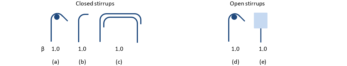
\[ \textsf{\textit{\footnotesize{Fig. 18\qquad Available anchorage types and respective anchorage coefficients for stirrups.}}}\]
\[ \textsf{\textit{\footnotesize{Closed stirrups: (a) hook; (b) bend; (c) overlap. Open stirrups: (d) hook; (e) continuous bar.}}}\]
The intended reduction in lb,net is equivalent to the activation of the reinforcing bar at its end at a percentage of its maximum capacity given by the anchorage reduction coefficient, as shown in Fig. 19a.

\[ \textsf{\textit{\footnotesize{Fig. 19\qquad Model for the reduction of the anchorage length:}}}\]
\[ \textsf{\textit{\footnotesize{(a) anchorage force along the anchorage length of the reinforcing bar; (b) slip-anchorage force constitutive relationship.}}}\]
The reduction of the anchorage length is included in the finite element model by means of a spring element at the end of the bar (Fig. 15), which is defined by the constitutive model shown in Fig. 19b. The maximum force transmitted by this spring (Fau) is:
\[F_{au} = \beta \cdot A_s \cdot f_{yd}\]
where :
β the anchorage coefficient based on anchorage type,
As the cross-section of the reinforcing bar,
fyd the design value of the yield strength of the reinforcement.