Permanent service bridge truss, Heathrow Airport, UK
The design of the main structure was made by Mott MacDonald as the original consulting company. Τhe contractor responsible for the construction was DHD Engineering, who assigned our client, Ellis & Moore Consulting Engineers the design of the connections.
In this article, we will explain the challenging parts of this particular connection design and how they were successfully solved with IDEA StatiCa Connection, whilst we are going to assess the use of the original component method that is implemented in the Eurocode and prove that its application is almost impossible in this particular case.

Joint classification for manual design
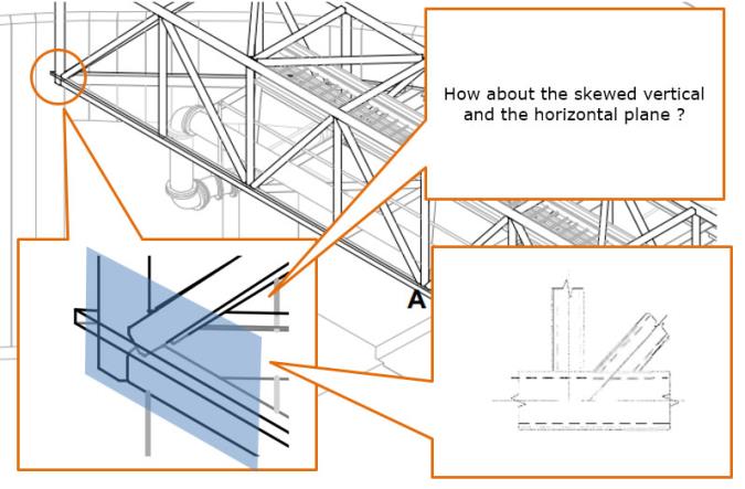
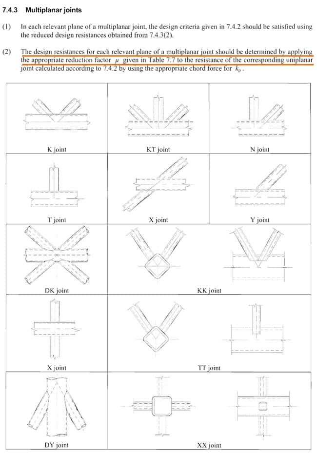
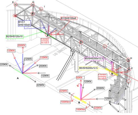
First, we will try to explain the procedure when a complex connection needs to be designed manually. We will use as an example of the N-joint that is shown in the picture on the right, which is a multiplanar joint. In order to perform a proper calculation by using the component method, we need to recognize the relevant configuration in Figure 7.1 of the Eurocode (click the picture below).
From the geometry of the connection, we can see that along the longitudinal direction marked with the light blue rectangle there were no problems. It can be clearly classified as an N joint. The problems start at the skewed plane! So, eventually, we have two coexisting “N” joints with a “Y” joint.
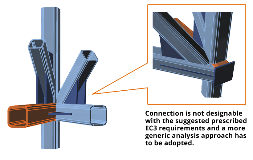
Along this direction, the problem can be easily visualized by using the realistic 3D view screenshot taken from the final IDEA StatiCa Connection model (see below). For this particular configuration, there is no clear guidance in the code and/or the limits required by the relevant paragraphs for overlaps, etc. are not necessarily kept. In this case, you either need some expert advice and proper engineering judgment if you were to use the component method. Moreover, since the screenshots are taken from the finalized connection, we can see that various reinforcing gussets were used in order to reinforce the connection and reach the required resistance. The existence of these gussets alone makes the connection undesignable with the application of the component method.
Successful design with the CBFEM method
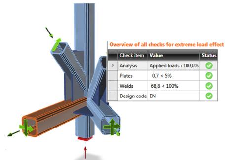
These limitations of the component method do not apply to CBFEM and IDEA StatiCa Connection, simply because the joint is modeled exactly as it is in reality and is analyzed as a unifying element in all directions, with finite elements. So, after all the forces have been applied, the model can be solved, all the internal forces that interact in our model are calculated, and we immediately can get a quick overview of all the Eurocode checks that shows a safe design.
What’s also important compared to the component method is that this workflow is common among all connection types. So, if for example the rectangular sections for some reason were changed to circular or I type section, no special consideration has to be taken into account. This is not the case with the component method which has special rules for each kind of cross-section.
A note about the design of connections in the UK
We could safely say that when it comes to steel connection design, structural engineers follow a certain procedure that seems to be a common practice in the UK. In order to design the connections, the engineers responsible for the basic design of the structure provide markups like the one in the picture on the right. In order to have human-readable information, connections are grouped. Then, for each group, an envelope of acting forces is created. This procedure provides an overstrength to the connection that leads to a safe design, but also makes the information flow easier between the two parties. The problem with this approach is that the required overstrength (at least in this particular case) is so big that without the provided reinforcing gussets the welded members would be unable to resist the provided forces.
This means that the connection designer is sometimes in front of a dead-end because changing the size of the member is not an acceptable practice and if it happens it must be properly justified. In this particular case, using IDEA StatiCa Connection was the client’s only way to achieve the required design without using complex FEM analysis and the pitfalls that follow its application.
More economical design with IDEA StatiCa Connection
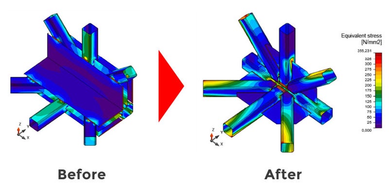
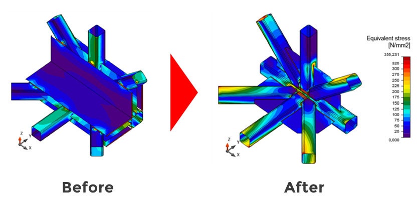
This common practice that was described previously, was also used initially in this project. As a consequence, the envelope design forces that were provided by the original consulting engineers resulted in a very uneconomical design of the trusses’ primary joints. As you can see in the picture below, the preliminary/feasibility design yielded a very heavy connection for a joint with 8 members, which is located in the middle of the span.

After intermediate communication with the main consulting engineers, forces have been amended to produce more realistic combinations and feasible designs. These forces have been used in IDEA StatiCa Connection, and then a more economical design has been achieved, with less additional plates used. The outcome of this new approach and communication between the two parties is illustrated below:
Although it was the first major project that we used IDEA StatiCa Connection, the general philosophy and practices of the software helped us to quickly elaborate with such complex connections, which we would have normally designed by hand. In IDEA StatiCa Connection, all these connections became solvable, and even better, there is no special consideration to be taken care of. The workflow is common no matter what the geometry is.
Another important thing was that the reasonable connection details lead to reduced manufacturing costs, and the assembly of the trusses was relatively easy.
So the project has been considered a success for all parties… and the next phase of the job is undertaken by the same team... with similar challenges for the detailers.
Alexander Bezas
Eur Ing, BEng Hons / MSc Civil engineer
Senior Structural Engineer at Ellis and Moore Consulting Engineer