Malla triangular en el elemento de hormigón
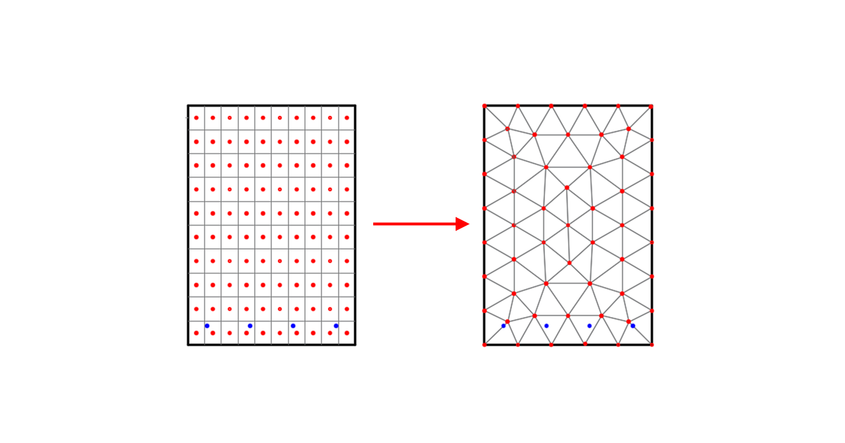
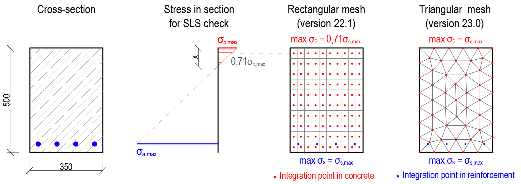
Se ha implementado una malla triangular para secciones transversales en la aplicación Member para elementos de hormigón. La malla rectangular que se utilizaba anteriormente era suficiente para elementos en flexión solo si se definía una malla muy fina. La razón es que los resultados se calculan en los puntos de integración ubicados en el centro de gravedad de cada elemento finito, por lo que no calculamos la tensión real en el borde de la sección transversal. Los resultados son entonces muy sensibles al tamaño de la malla, especialmente para elementos en flexión, para los cuales la zona comprimida en el hormigón podría tener solo unos pocos centímetros de altura. Por lo tanto, muchos elementos finitos provocan una ralentización del cálculo, así como de la presentación de los resultados en la escena 3D.
Todos estos problemas se han resuelto implementando la malla triangular para secciones calculadas mediante el análisis MNA y GMNIA. Los puntos de integración se ubican en los nodos (vértices de los elementos finitos), por lo que obtenemos resultados en el borde de la sección transversal para capturar los picos de tensión en el hormigón debidos a la flexión. Esto aporta muchas ventajas a los usuarios. Los resultados no son sensibles al tamaño de la malla, por lo que, de forma predeterminada, la malla es gruesa (en comparación con la malla rectangular), lo que lleva a reducir el tiempo de cálculo y una respuesta más rápida de la aplicación al trabajar con resultados junto con resultados más precisos y seguros.
Disponible en la edición Enhanced de IDEA StatiCa Concrete