Îmbinări precalificate pentru aplicații seismice
12.1 Proiectul EQUALJOINTS
Proiectul european de cercetare EQUALJOINTS furnizează criterii de precalificare a îmbinărilor metalice pentru viitoarea versiune a EN 1998-1. Activitatea de cercetare a acoperit standardizarea procedurilor de proiectare și fabricație pentru un set de tipuri de îmbinări cu șuruburi și o secțiune de grindă redusă sudată cu profile grele, proiectate pentru a satisface diferite niveluri de performanță. De asemenea, a fost elaborat un nou protocol de încărcare pentru precalificarea europeană, reprezentativ pentru cerința seismică europeană. Campania experimentală dedicată caracterizării ciclice atât a oțelului carbon moale european, cât și a șuruburilor de înaltă rezistență a obținut comportamentul necesar pentru patru tipuri de îmbinări precalificate: îmbinări cu șuruburi și vută, îmbinări cu placă de capăt extinsă nerigidizată cu șuruburi, îmbinări cu placă de capăt extinsă rigidizată cu șuruburi și îmbinări cu secțiune de grindă redusă sudată; a se vedea Fig. 12.1.1. Rezultatele obținute experimental în cadrul proiectului EQUALJOINTS sunt rezumate în (Stratan et al. 2017) și (Tartaglia și D'Aniello, 2017).

Fig. 12.1.1 Îmbinări structurale precalificate în proiectul EQUALJOINTS
12.2 Îmbinări cu placă de capăt
Îmbinările cu șuruburi și placă de capăt extinsă rigidizată sunt cele mai frecvente în industria europeană de fabricație a structurilor metalice și sunt utilizate pe scară largă în practica europeană ca îmbinări rezistente la moment în cadre metalice cu înălțime mică și medie, datorită simplității și economiei de fabricație și montaj. Criteriile de proiectare și cerințele aferente pentru îmbinările grindă-stâlp cu șuruburi și placă de capăt extinsă rigidizată sunt investigate în profunzime și discutate critic, fiind în prezent codificate în EN 1998-1:2005 pe baza unui studiu parametric bazat pe analize cu elemente finite. Din păcate, procedura de proiectare prin capacitate a fost dezvoltată doar în cadrul metodei componentelor. Aceasta ține cont și de prezența nervurilor și este capabilă să controleze răspunsul îmbinării pentru diferite niveluri de performanță.
Îmbinările cu placă de capăt extinsă nerigidizată sunt utilizate frecvent în construcțiile metalice pentru a conecta grinzi cu secțiune I sau H la stâlpi cu secțiune I sau H, în cazurile în care trebuie transferate momente încovoietoare semnificative. Această configurație permite un montaj facil prin înșurubare, în timp ce sudarea plăcii de capăt la grindă este automatizată în atelier. Rezistența la încovoiere a îmbinării este în general mai mică decât rezistența la încovoiere a elementelor conectate. Prin urmare, astfel de îmbinări sunt considerate cu rezistență parțială. Atingerea unei situații de rezistență egală, în care rezistența plastică a îmbinării este aproximativ egală cu rezistența plastică a secțiunii grinzii, poate fi obținută printr-o proiectare adecvată. Ductilitatea lor la încovoiere depinde în mare măsură de detaliile de alcătuire ale îmbinărilor, care influențează modul de cedare (Jaspart, 1997). Dacă componenta îmbinării care guvernează cedarea este una ductilă și dacă rezistența componentelor active fragile este semnificativ mai mare, se poate obține un răspuns ductil al îmbinării. În caz contrar, nu trebuie să se bazeze pe capacitatea îmbinării de a forma articulații plastice și de a redistribui eforturile interne pentru a absorbi energia într-o zonă seismică.
Pentru îmbinările cu moment rezistent și secțiune de grindă redusă sudată, cunoscute și sub denumirea de „dog-bone", au fost adoptate două strategii principale: consolidarea îmbinării sau slăbirea grinzii. Dintre cele două opțiuni pentru profilul reducerii de secțiune, tăierea cu rază tinde să prezinte un comportament relativ mai ductil, întârziind fractura finală (Jones et al. 2002). Cu toate acestea, studiul a arătat că elementele cu secțiune de grindă redusă sunt mai predispuse la flambaj lateral-torsional din cauza reducerii ariei tălpilor. Cercetările experimentale și analitice ulterioare axate pe utilizarea stâlpilor cu înălțime mare (Zhang și Ricles, 2006) au indicat că prezența unei plăci de planșeu compozite poate reduce semnificativ torsiunea care se dezvoltă în stâlp, deoarece oferă contravântuire grinzii și reduce deplasarea laterală a tălpii inferioare.
Conform procedurii de proiectare dezvoltate în cadrul proiectului EQUALJOINTS, îmbinarea cuprinde trei macro-componente: panoul inimii stâlpului, zona de îmbinare și zona grinzii; a se vedea Fig. 12.2.1. Fiecare macro-componentă este proiectată individual conform unor ipoteze specifice, după care se aplică criteriile de proiectare prin capacitate pentru a obține trei obiective de proiectare diferite, definite pentru evaluarea îmbinării: îmbinări cu rezistență totală, cu rezistență egală și cu rezistență parțială. Îmbinările cu rezistență totală sunt proiectate pentru a garanta formarea tuturor deformațiilor plastice în grindă, ceea ce este consistent cu regulile de proiectare prin capacitate „stâlp puternic – grindă slabă" din EN 1998-1:2005. Îmbinările cu rezistență egală sunt caracterizate teoretic prin curgerea simultană a tuturor macro-componentelor, respectiv îmbinarea, panoul inimii și grinda. Îmbinările cu rezistență parțială sunt proiectate pentru a dezvolta deformația plastică doar în îmbinare sau în panoul inimii stâlpului. În funcție de rezistența macro-componentelor îmbinării și ale panoului inimii stâlpului, atât pentru îmbinările cu rezistență egală, cât și pentru cele cu rezistență parțială, poate fi introdusă o clasificare suplimentară. Pentru un panou de inimă puternic, cererea plastică este concentrată în îmbinare pentru îmbinarea cu rezistență parțială sau în îmbinare și în grindă pentru îmbinarea cu rezistență egală. Pentru un panou de inimă echilibrat, cererea plastică este distribuită între îmbinare și panoul inimii stâlpului pentru îmbinarea cu rezistență parțială și în îmbinare, panoul inimii și grindă pentru îmbinarea cu rezistență egală. Pentru un panou de inimă slab, cererea plastică este concentrată în panoul inimii stâlpului pentru îmbinarea cu rezistență parțială sau în panoul inimii și în grindă pentru îmbinarea cu rezistență egală.

Fig. 12.2.1 Împărțirea îmbinării în macro-componente
Ductilitatea îmbinării depinde de tipul modului de cedare și de capacitatea de deformație plastică corespunzătoare a componentei activate. Capacitatea de deformație poate fi estimată aproximativ prin satisfacerea criteriilor dezvoltate pentru metoda componentelor (CM) sau calculată mai precis prin CBFEM. Mai jos sunt prezentate exemple de proiectare a două configurații de îmbinări precalificate descrise în materialele proiectului EQUALJOINTS și în standardul ANSI/AISC358-16, luând în considerare comportamentul macro-componentelor în mod separat.
12.2.1 Validare
Modelele CBFEM privind rigiditatea, capacitatea portantă și capacitatea de deformație a îmbinărilor precalificate au fost validate de Montenegro (2017) pe un set de experimente disponibile din proiectul EQUALJOINTS. Exemple de soluții structurale sunt prezentate în Fig. 12.2.2. Rezultatele validării modului de cedare sunt prezentate în Fig. 12.2.3. Sinteza validării rezistenței și a capacității de deformație pentru o deformație de 15 % este prezentată în Fig. 12.2.4 și Fig. 12.2.5.

Fig 12.2.2 Îmbinări utilizate pentru validare și verificare a) EH2-TS-35-M și EH2-TS-45-M, b) ES1-TS-F-M și ES3-TS-F-M, c) E1-TS-E-M și E2-TS-E-M
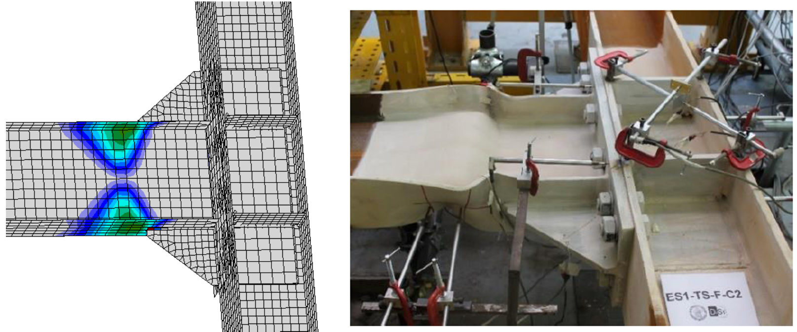
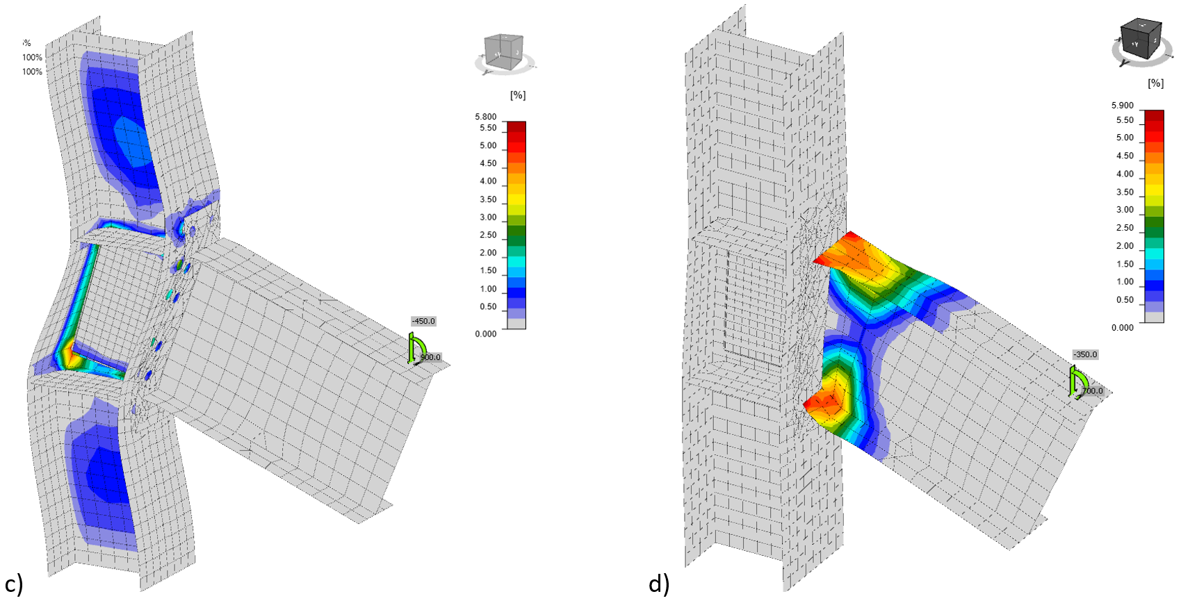
Fig. 12.2.3 Validarea modului de cedare CBFEM pe îmbinările cu placă de capăt extinsă și vută E1-TS-F-C2 (Tartaglia și D'Aniello, 2017)

Fig.12.2.4 Validarea rezistenței CBFEM pe experimente din proiectul EQUALJOINTS

Fig. 12.2.5 Validarea capacității de rotație CBFEM pe experimente din proiectul EQUALJOINTS
12.2.2 Verificare
Modelul CBFEM a fost verificat față de metoda componentelor (CM) conform Cap. 6 din EN 1993-1-8:2006. Selecția rezultatelor este prezentată în Tab. 12.2.1 și Fig. 12.2.6. Rezultatele evidențiază pierderea preciziei metodei CM pentru îmbinările de dimensiuni mai mari, unde ipoteza aproximativă privind brațul de pârghie influențează acuratețea.
Tab. 12.2.1 Verificarea CBFEM față de CM
| Tipologie | Rezistență | |||
| # | CM | CBFEM | CBFEM/CM | Componentă decisivă |
| MR [kNm] | MR [kNm] | [%] | ||
| Îmbinare cu vută | ||||
| EH2-TS35-M | 901,2 | 889 | 1 | Placă de capăt la încovoiere |
| EH2-TS45-M | 959,3 | 875 | 10 | Placă de capăt la încovoiere |
| 4.2 | 876,1 | 1 016 | −16 | Talpa stâlpului la încovoiere |
| 264 | 545,4 | 573 | −5 | Talpa stâlpului la încovoiere |
| 267 | 1 998,9 | 2 100 | −5 | Placă de capăt la încovoiere |
| Îmbinare extinsă rigidizată | ||||
| ES1-TS-F-M | 547,5 | 533 | 3 | Talpa stâlpului la încovoiere |
| ES3-TS-F-M | 1389 | 1 920 | −27 | Talpa stâlpului la încovoiere |
| Îmbinare extinsă nerigidizată | ||||
| E1-TB-E-M | 347,8 | 389 | −11 | Placă de capăt la încovoiere |
| E2-TB-E-M | 577,0 | 681 | −15 | Placă de capăt la încovoiere |

Fig. 12.2.6 Verificarea rezistenței CBFEM față de CM
Trei îmbinări cu vută unilaterală sunt descrise mai detaliat în (Landolfo et al. 2017) și (aplicația Equaljoints). Îmbinările sunt încărcate atât cu momente încovoietoare pozitive, cât și negative și cu forța tăietoare corespunzătoare. Inimile stâlpilor sunt consolidate cu dubluri, astfel încât componentele decisive sunt T-stub-urile fie ale plăcii de capăt, fie ale tălpii stâlpului. Axele de rotație sunt presupuse la centrul tălpii superioare a grinzii pentru momentul încovoietor pozitiv și la mijlocul vutei pentru momentul încovoietor negativ. Poziția articulației plastice este presupusă la fața plăcii de rigidizare de la capătul vutei. Momentul încovoietor la fața stâlpului utilizat pentru verificarea îmbinării este majorat cu forța tăietoare corespunzătoare; a se vedea Fig. 12.2.7.

Fig. 12.2.7 Poziția articulației plastice, diagrama momentului încovoietor în îmbinarea cu vută
Tab. 12.2.2 Rezistența componentelor prin CM pentru îmbinările cu vută
| Rezistența componentelor prin CM | #4.2 (IPE450 la HEB340) | #264 (IPE360 la HEB280) | #267 (IPE600 la HEB500) |
| Moment la articulația plastică [kNm] | 906 | 543 | 1869 |
| Forță tăietoare [kN] | 295 | 148 | 561 |
| Moment la fața stâlpului [kNm] | 981 | 573 | 2105 |
| Rezistența vutei [kNm] | 956 | 582 | 1903 |
| Forța tăietoare care acționează pe inima stâlpului [kN] | 1581 | 1035 | 2447 |
| Rezistența inimii stâlpului la forfecare [kN] | 1632 | 1203 | 2774 |
| T-stub - placă de capăt - moment negativ [kNm] | 1019 | 573 | 1999 |
| T-stub - placă de capăt - moment pozitiv [kNm] | 1081 | 697 | 2318 |
| T-stub - talpa stâlpului - moment negativ [kNm] | 876 | 545 | 2015 |
| T-stub - talpa stâlpului - moment pozitiv [kNm] | 929 | 580 | 2107 |
Factorul de ecruisare a fost ales 1,2 conform recomandărilor din EN 1993-1-8:2006 și raportul final al proiectului Equaljoints (EN 1998-1:2005 sugerează valoarea 1,1). Factorul de suprarezistență a fost presupus 1,25 (Landolfo et al. 2017). Tot oțelul a fost de clasa S355. Rezistențele componentelor individuale sunt rezumate în Tab. 12.2.2. Verificările marcate cu bold nu sunt satisfăcute. De remarcat că rezistența vutei reprezintă rezistența plastică a secțiunii grinzii cu vuta la placa de capăt. Rezistența grinzii este presupusă majorată cu factorul de suprarezistență la locul articulației plastice, dar nu și la placa de capăt. Dacă factorul de suprarezistență ar fi aplicat și la placa de capăt, această rezistență ar fi mai mare. Prin urmare, următoarea rezistență cea mai mică, T-stub – placă de capăt, a fost considerată ca guvernând rezistența îmbinării nr. 267. Niciuna dintre îmbinările investigate nu satisface cerința pentru îmbinare cu rezistență totală. Cu toate acestea, rezistența este foarte apropiată, iar îmbinările sunt cu rezistență egală. Panoul inimii stâlpului este puternic în toate cazurile.
Modul de cedare determinant conform CBFEM este cedarea șuruburilor cu curgerea plăcilor, în principal a plăcii de capăt, a tălpii stâlpului și a vutei. Conform CBFEM, îmbinările nr. 4.2 și nr. 264 sunt cu rezistență totală, iar îmbinarea nr. 267 este cu rezistență egală. Panourile inimii stâlpului sunt puternice în toate cazurile.


Fig. 12.2.8 Deformațiile la rezistență pentru a) întreaga îmbinare, b) numai macro-componenta îmbinare cu placă de capăt cu șuruburi, c) numai macro-componenta panou de inimă al stâlpului la forfecare cu dubluri de inimă, d) numai macro-componenta grindă
12.2.3 Îmbinări cu placă de capăt extinsă nerigidizată
Pentru studiul de sensibilitate, a fost selectată o îmbinare precalificată cu placă de capăt extinsă nerigidizată. Grinda IPE 450 este conectată la stâlpul HEB 300 printr-o placă de capăt extinsă cu grosimea de 25 mm cu douăsprezece șuruburi M30 10.9, cu și fără dublură de inimă de 10 mm grosime. Oțelul de clasa S 355 a fost utilizat pentru toate plăcile. Pentru a determina contribuția fiecărei macro-componente în mod separat, diagrama de material a macro-componentei selectate a fost elastoplastică, în timp ce restul îmbinării a avut doar diagramă de material elastică. Deformațiile la rezistența întregii îmbinări, a panoului inimii stâlpului la forfecare numai cu dubluri de inimă și a îmbinării cu placă de capăt cu șuruburi sunt comparate cu macro-componenta grindă în Fig. 12.2.8. Influența fiecărei macro-componente asupra comportamentului îmbinării este prezentată în Fig. 12.2.9, unde panoul inimii stâlpului cu și fără dubluri de inimă este ilustrat. Comportamentul îmbinării evidențiază o rezistență mai mare a macro-componentei îmbinare.

Fig. 12.2.9 Influența macro-componentelor, panoul inimii stâlpului cu dubluri la forfecare,
îmbinarea cu placă de capăt cu șuruburi și grinda asupra comportamentului întregii îmbinări
12.2.4 Localizarea centrului de compresiune
Pentru îmbinările cu placă de capăt, EN 1993-1-8:2006 specifică faptul că centrul de compresiune este situat la mijlocul grosimii tălpii grinzii sau la vârful vutei în cazul îmbinărilor cu vută. Rezultatele experimentale și numerice au arătat că localizarea centrului de compresiune depinde atât de tipul îmbinării, cât și de cererea de rotație, datorită formării modurilor plastice cu angajare diferită a fiecărei componente a îmbinării (Landolfo et al. 2017). Conform procedurii de proiectare CM propuse și pe baza rezultatelor atât experimentale, cât și numerice, se estimează un contact în apropierea centroidului secțiunii formate din talpa grinzii și nervurile de rigidizare, pentru îmbinările cu placă de capăt rigidizată, sau la aproximativ 0,5 din înălțimea vutei în cazul îmbinărilor cu vută. Această ipoteză aproximativă este precizată de procedura CBFEM, care furnizează valori corecte în timpul încărcării și al curgerii inițiale a părților îmbinării.
Rezultatele prezentate demonstrează acuratețea bună a CBFEM verificat față de ROFEM și validat pe experimentele EQUALJOINTS și CM. Aceasta oferă posibilitatea de a considera comportamentul macro-componentelor în mod separat și poziția axelor neutre cu precizie în funcție de încărcare/plastificare.
12.3 Îmbinare cu secțiune de grindă redusă sudată
O îmbinare precalificată cu secțiune de grindă redusă sudată conform ANSI/AISC 358-16 a fost selectată pentru acest studiu. Grinda IPE 450 este conectată la stâlpul HEB 300 prin suduri cap la cap la tălpi și o placă de inimă de 12 mm grosime cu trei șuruburi pretensionate M30 10.9, cu și fără dublură de inimă de 10 mm grosime; a se vedea Fig. 12.3.1. Tot oțelul utilizat este de clasa S355.
Deformațiile la rezistența ultimă a întregii îmbinări și ale macro-componentei panou de inimă al stâlpului la forfecare numai cu dubluri de inimă sunt prezentate în Fig. 12.3.2. Influența fiecărei macro-componente asupra comportamentului îmbinării este prezentată în Fig. 12.3.3, unde panoul inimii stâlpului cu și fără dubluri de inimă este ilustrat. Îmbinarea arată că rezistențele macro-componentelor sunt bine optimizate.
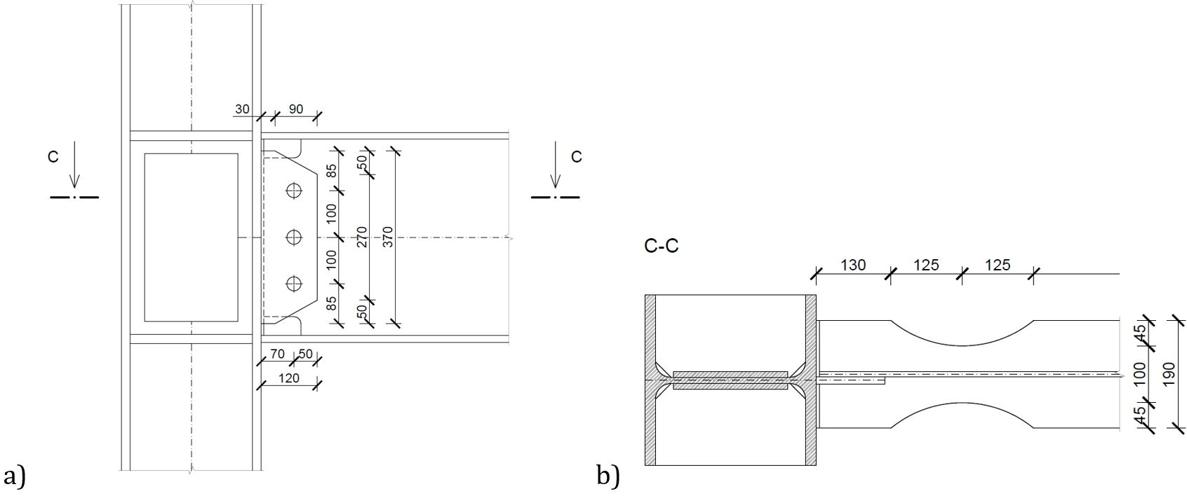
Fig. 12.3.1 Îmbinare cu secțiune de grindă redusă, a) grindă cu secțiune redusă, b) panoul inimii stâlpului cu dubluri la forfecare, îmbinarea cu placă de capăt cu șuruburi,

Fig. 12.3.2 Deformațiile la rezistență pentru a) întreaga îmbinare și b) numai macro-componenta panou de inimă al stâlpului cu dubluri la forfecare

Fig. 12.3.3 Influența macro-componentelor asupra comportamentului întregii îmbinări pe diagrama M-φ
Referințe
EN 1993-1-8, Eurocode 3, Proiectarea structurilor de oțel – Partea 1-8: Proiectarea îmbinărilor, CEN, Bruxelles, 2005.
Jones S.L., Fry GT., Engelhardt M.D. Evaluare experimentală a îmbinărilor cu moment rezistent și secțiune de grindă redusă solicitate ciclic. Journal of Structural Engineering. 128 (4), 441–451, 2002.
Landolfo R. et al. Proiectarea structurilor de oțel pentru clădiri în zone seismice, Manual de proiectare ECCS Eurocode. Wiley, 2017.
Stratan A., Maris C, Dubina D, și Neagu C. Precalificarea experimentală a îmbinărilor grindă-stâlp cu șuruburi și placă de capăt extinsă cu vute. ce/papers, 1(2–3), 414–423, 2017.
Tartaglia R, D'Aniello M. Comportamentul neliniar al îmbinărilor grindă-stâlp cu șuruburi și placă de capăt extinsă rigidizată supuse eliminării stâlpului. The Open Civil Engineering Journal Vol 11, Issue Suppl-1, 369–383, 2017.
Zhang X., Ricles J.M. Evaluare experimentală a îmbinărilor cu secțiune de grindă redusă la stâlpi cu înălțime mare. Journal of Structural Engineering. 132 (3), 346-357, 2006.