A "walking column" is a type of structural column that shifts horizontally between floors, meaning it is not vertically aligned with the columns below it (see Figure 4.1). This lateral shift typically occurs due to architectural or design requirements, allowing flexibility in floor layouts while still transferring loads through the structure. Despite this lateral offset, walking columns are engineered to ensure they effectively carry vertical loads across different levels.
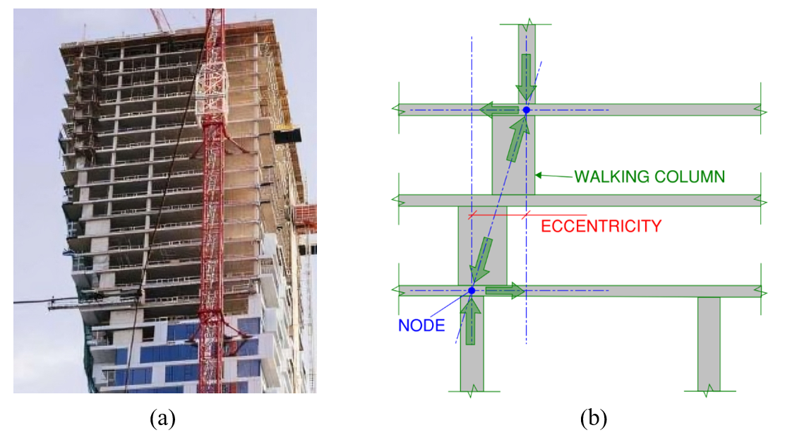
Figure 4.1: Walking column: a) Walking column in real building, and b) load transfer mechanism of walking column (SheerForce Engineering, 2021).
The vertical load capacities of these columns were assessed through IDEA StatiCa software and subsequently compared with design capacities derived from the Strut-and-Tie Model (STM) as outlined in ACI 318-19 (2019). One of the four walking column examples was chosen as a baseline for further analysis using ABAQUS software (2023), where its load-bearing capacity, principal stress distribution, and crack patterns were determined and compared to the results obtained from both the Compatible Stress Field Method (CSFM) and ACI 318-19 design procedure.
Walking columns in modern buildings
To assess the structural performance of walking columns, four RC walking columns, identified as Examples 1 through 4, were evaluated. These columns were designed and presented by Schwinger (2021) at a seminar organized by the Delaware Valley Association of Structural Engineers, Eastern Chapter of the Structural Engineers Association of Pennsylvania. The primary objective of these design examples was to provide design guidelines for engineers, due to the lack of experimental studies or design data specifically focusing on walking columns.
The 56 Leonard Building
The 56 Leonard, located in Manhattan, New York, was constructed in 2016. It is a striking example of the application of walking columns in modern architecture (Figure 4.2). Floors of the 821-ft tall and 60-story building appear irregularly stacked, reminiscent of a "Jenga" game (Lubell, 2015).
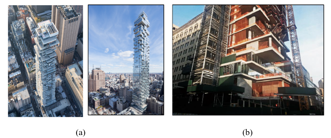
Figure 4.2: Walking column example: a) 56 Leonard building, and b) walking columns.
Chicago Mercantile Exchange Center
The Chicago Mercantile Exchange Center (CME), completed in 1987, is a prime example of how walking columns can be integrated into a structural design to handle complex load distributions in large commercial buildings (Figure 4.3). The building features two 40-story towers connected by a 10-story base structure, designed to accommodate the functional requirements of a trading exchange, such as large open trading floors on the lower levels. To achieve this, a robust transfer load system was employed, utilizing walking columns to transfer the loads from the upper levels to the foundation.
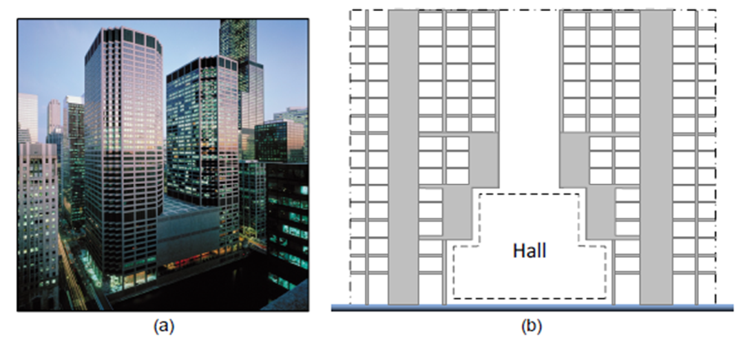
Figure 4.3: a) Chicago Mercantile Exchange Center, and b) its elevation view and load transfer mechanism.
Beetham Tower
Beetham Tower in Manchester, UK, completed in 2004, is a notable example of a structure utilizing walking columns to achieve both structural and aesthetic objectives (Figure 4.4). At 168 meters (551 ft) tall, it was one of the highest residential buildings in Europe at the time of its completion.
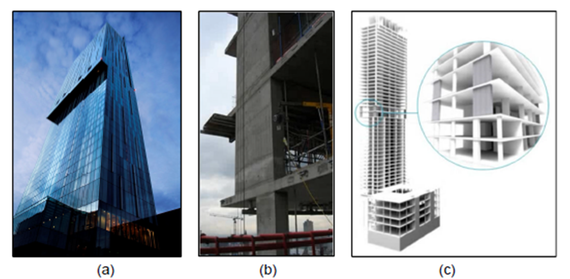
Figure 4.4: a) Beetham Tower, b) walking column, and c) walking column scheme.
Miami Tower
The 47-story Miami Tower in Miami Florida was completed in 1987 and includes unique setbacks and stepped profile (Figure 4.5). These features required an innovative structural design solution to manage the different load paths throughout the building. Walking columns were used to transfer loads from the smaller upper floors to the larger base below. The Miami Tower illustrates how walking columns can be effectively used in high-rise construction to achieve both functional and visual goals , 1987).
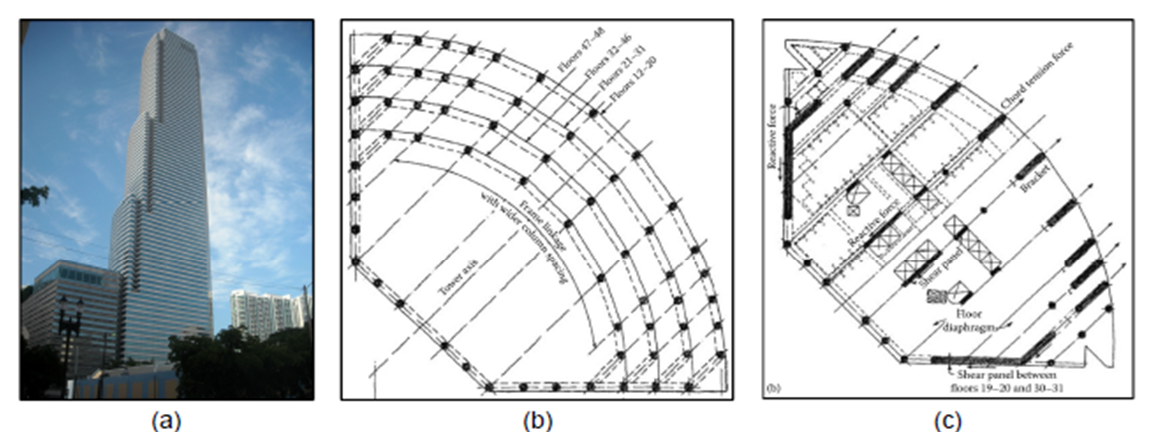
Figure 4.5: a) Miami Tower, b) structural floor layout, and c) walking column layout (Taranath, 2010).
ABAQUS Model Development and Analysis
The walking column from Example 1 was modeled using the ABAQUS software (2023) for finite element (FE) analysis. Example 1 is also modeled using IDEA StatiCa and analyzed in Section 4.5.1. The results from ABAQUS analysis are compared with those obtained from IDEA StatiCa in Section 4.7 of the complete study.
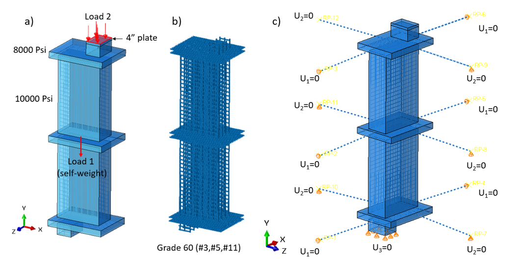
Figure 4.10: Model setup in ABAQUS showing: a) the locations and details of the applied load, b) reinforcement bars details, and c) boundary conditions.
The calculated and predicted directions of principal stresses from IDEA StatiCa (see Section 4.5.1) and ABAQUS, respectively, are presented in Figure 4.15. Both models offer comparable results, resembling bottle-shaped struts. This suggests that the overall response of the specimen is consistent between the two models, supporting the use of the calculated response to develop a more realistic strut-and-tie model (as done in Section 4.6).
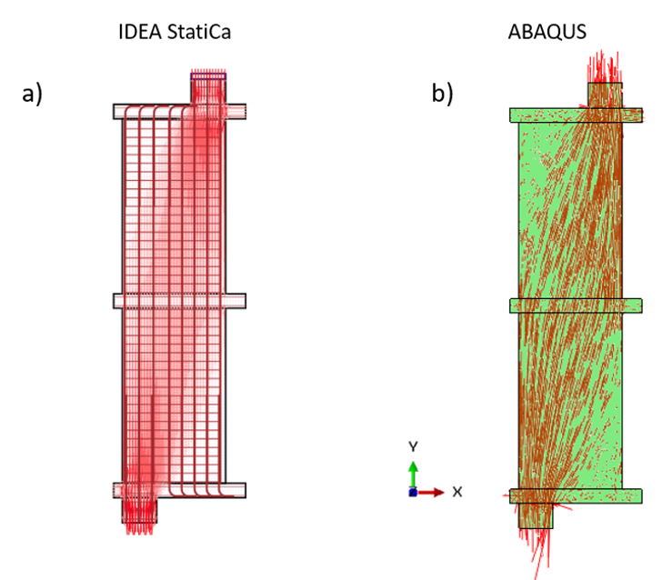
Figure 4.15: Comparison of the direction of principal stresses calculated using the IDEA StatiCa and ABAQUS models.
IDEA StatiCa Analysis
The behavior of reinforced concrete walking columns (Examples 1 through 4, as described in Section 4.5) was analyzed using IDEA StatiCa software. These designs were selected to examine the effect of vertical load transfer mechanism on their structural performance. The modeling approach employed in IDEA StatiCa incorporated the specified compressive strength of concrete and the yield and ultimate strengths of the reinforcing steel bars, adhering to the parameters established by Schwinger (2021).
In the IDEA StatiCa analysis, load factors of 1.0 were applied to both load patterns—the self-weight and the applied vertical load—reflecting actual behavior without factoring for design safety. To determine the design and actual capacities of the walking column, different material factors were applied: for concrete (ϕc), values of 0.65 for design capacity and 1.0 for actual capacity were used; similarly, for reinforcing steel (ϕs), factors of 0.9 for design and 1.0 for actual behavior were employed. It is important to clarify that ACI 318-19 prescribes different strength reduction factors depending on the failure mode, such as ϕ = 0.9 for bending, ϕ = 0.75 for shear, and ϕ = 0.65 for axial bearing, rather than uniform factors for all cases. However, in this study, uniform material’s strength reduction factors were employed within IDEA StatiCa to estimate the design capacity due to the lack of experimental data for the walking column. Currently, IDEA StatiCa software (version 24.0.6.1216) also does not provide the option to assign different strength reduction factors, ϕ for different failure conditions.
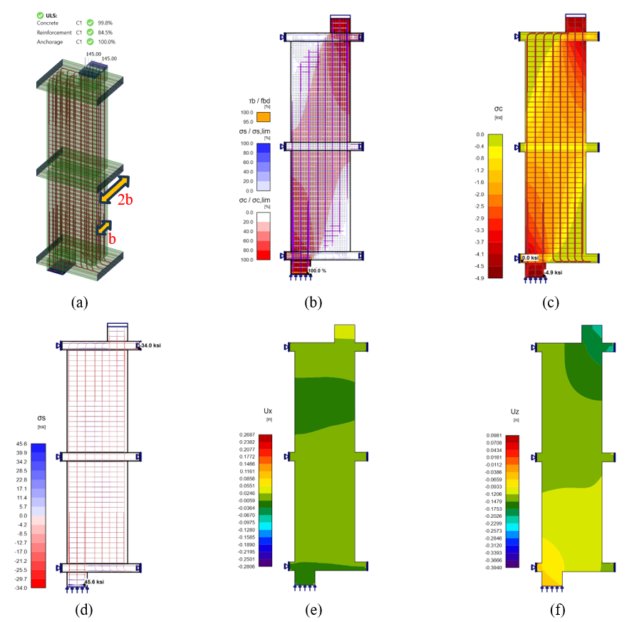
Figure 4.20: CSFM results for walking column Example 1: a) 3D view, b) stress flow, c) concrete principal stresses (σc), d) stresses in the reinforcement (σs), (e) displacement in x direction (Ux), and (f) displacement in z direction (Uz).
Capacity Calculation Using Strut and Tie Model
The capacity of the walking column examples was determined using the Strut and Tie Model (STM) methodology, as outlined in the ACI 318-19 code. The STM approach was applied to assess the performance of discontinuous regions, ensuring full compliance with the design principles established in Chapter 23 of ACI 318-19. By modeling force transfer through compressive struts and tensile ties, the STM method effectively represents the load distribution within the structure, particularly in areas with geometric discontinuities. For each walking column example, the design capacity was calculated using the STM framework, incorporating the appropriate strength reduction factors, ϕ as specified in ACI 318-19. The capacities of key structural elements within the walking columns were assessed, including:
- Capacity of the top column: The load-carrying capacity of the top column was calculated in accordance with the requirements for tied columns in ACI 318-19, taking into account both the concrete strength and the provided reinforcement.
- Capacity of the bottom column: Similarly, the capacity of the bottom column was calculated following the tied column provisions in ACI 318-19.
- Bearing capacity of the slabs: The bearing capacity of the slabs, located at the top and bottom of the columns, was evaluated to ensure sufficient concrete resistance against applied vertical forces.
- Vertical shear in the middle column/wall: The vertical shear capacity of the middle column or wall between the slabs was assessed to ensure that shear failure would not occur before the structure reaches its ultimate capacity.
The minimum capacity of these structural components was selected as the final design capacity for each walking column example, thereby identifying the most critical failure mode in accordance with ACI 318-19 code. In the analysis, the effective compressive strength of concrete, fce in the struts and nodal zones was calculated using the relevant equations from ACI 318-19, as detailed in Section 2.3 of Chapter 2 of this study. The strut and node confinement modification factor βc, strut coefficient βs, and nodal zone coefficient βn were determined using the values from Tables 2.1 to 2.3 in Chapter 2, respectively. The effective compressive strengths of concrete in strut and nodal zones were computed using Equations 2.4 and 2.9, respectively.
During the analysis, topology optimization techniques were employed to identify the most efficient stress flow paths within the structure. This process was carried out by IDEA StatiCa using effective volumes of 20% and 60%, which contributed to refining the STM design by optimizing load distribution through the struts and steel ties. This approach allowed for the creation of a more effective strut and tie model, with properly sized struts to ensure accuracy in force transmission.
Lastly, the STM models for each walking column example were developed utilizing stress flow diagrams and topology optimization plots generated through IDEA StatiCa software. These models provided a simplified yet precise representation of the load transfer mechanisms within the walking columns under the applied loads, effectively capturing the behavior of both compressive struts and tensile ties.
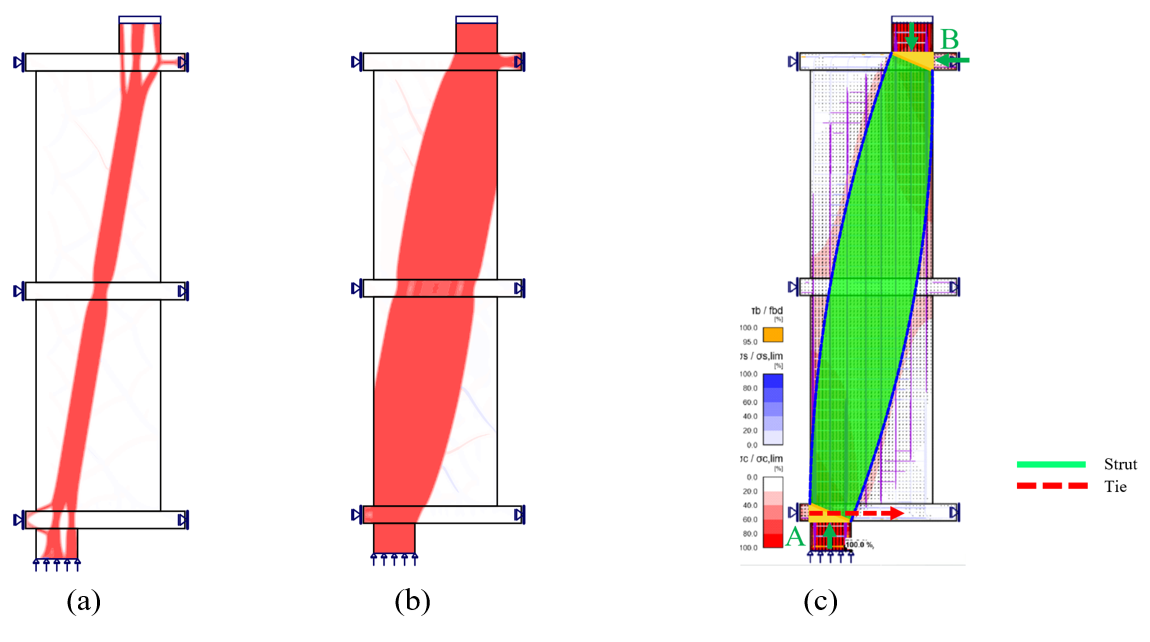
Figure 4.24: Strut and tie model for Example 1: a) topology optimization with 20% effective volume from IDEA StatiCa, b) topology optimization with 60% effective volume from IDEA StatiCa, and c) strut and tie model with stress flow.
Summary
The behavior of four walking column examples (Examples 1 through 4) was evaluated using the STM in accordance with ACI 318-19, along with IDEA StatiCa and ABAQUS. The baseline model, Walking Column Example 1, served as the reference for comparative analysis. A vertical load was applied to the top of each column to represent the design load, with strength reduction factors incorporated into the STM analysis based on ACI 318-19. Additionally, the maximum capacities of the walking columns were determined using the CSFM without the application of the ϕ values.
Table 4.3 compares the capacities of walking columns, evaluated using ACI 318-19, STM, and CSFM both with and without strength reduction factors, ϕ. The data reveal several patterns and distinctions in the behavior of the columns under varying analytical approaches. A detailed comparison of the results demonstrates that the capacities predicted by CSFM without ϕ are consistently higher than those obtained using STM and CSFM with ϕ, with variations depending on the specific example analyzed.
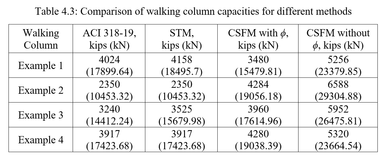
Table 4.3: Comparison of walking column capacities for different methods
In Figure 4.32, which provides a graphical comparison of the capacities across all methods and examples, the relationship between the different analytical approaches is clearly illustrated. The figure emphasizes the notable increases in capacity when strength reduction factors are not applied in the CSFM analysis. The visual representation distinctly shows how the capacities predicted by CSFM without ϕ values are consistently higher across all examples compared to both STM and ACI 318-19.
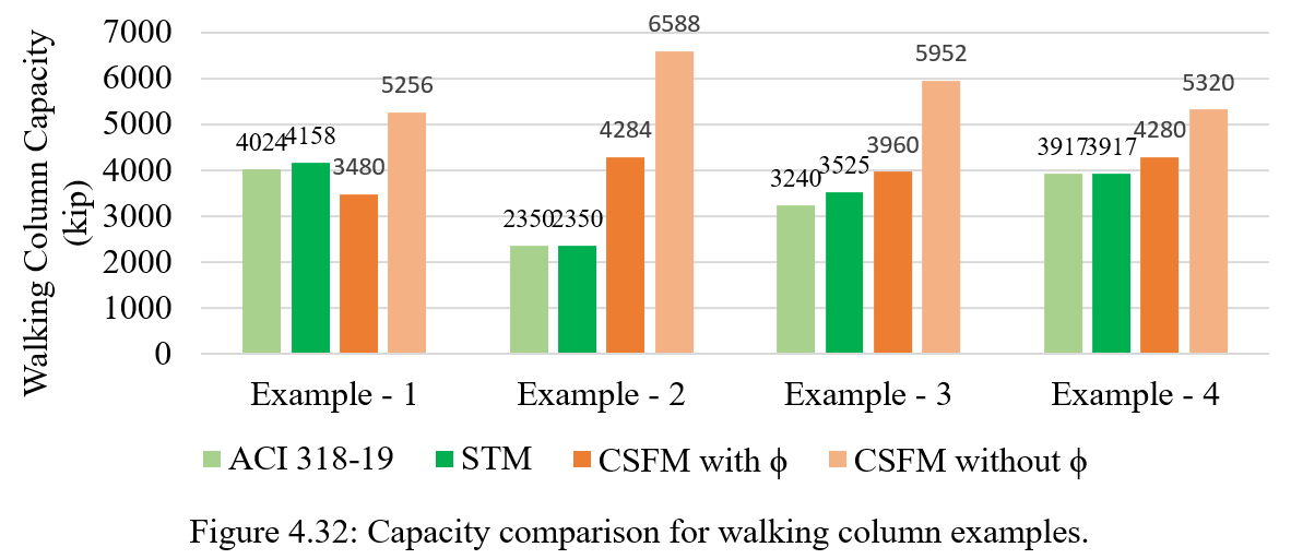
Figure 4.32: Capacity comparison for walking column examples.
In summary, the comparative analysis of the capacities of walking columns using ABAQUS, STM, and CSFM reveals notable patterns and relationships among these methods. The results indicate that ABAQUS consistently provides higher capacity estimates than both STM and CSFM, demonstrating its ability to capture complex material behaviors and loading conditions. The differences in capacities emphasize the conservative nature of the STM and CSFM with ϕ, which often leads to lower predictions compared to ABAQUS.
Overall, the CSFM analysis has proven to be a reliable tool for evaluating the capacities of walking columns. Its ability to offer insights into potential failure mechanisms and structural performance enhances its value in design applications. The flexibility of CSFM in adjusting for various loading scenarios and its sensitivity to strength reduction factors make it a beneficial method for structural engineers. Therefore, incorporating CSFM alongside other analytical approaches can lead to a more comprehensive understanding of the performance of walking columns, ultimately contributing to more robust and effective structural engineering practices.