Dimensionnement des soudures
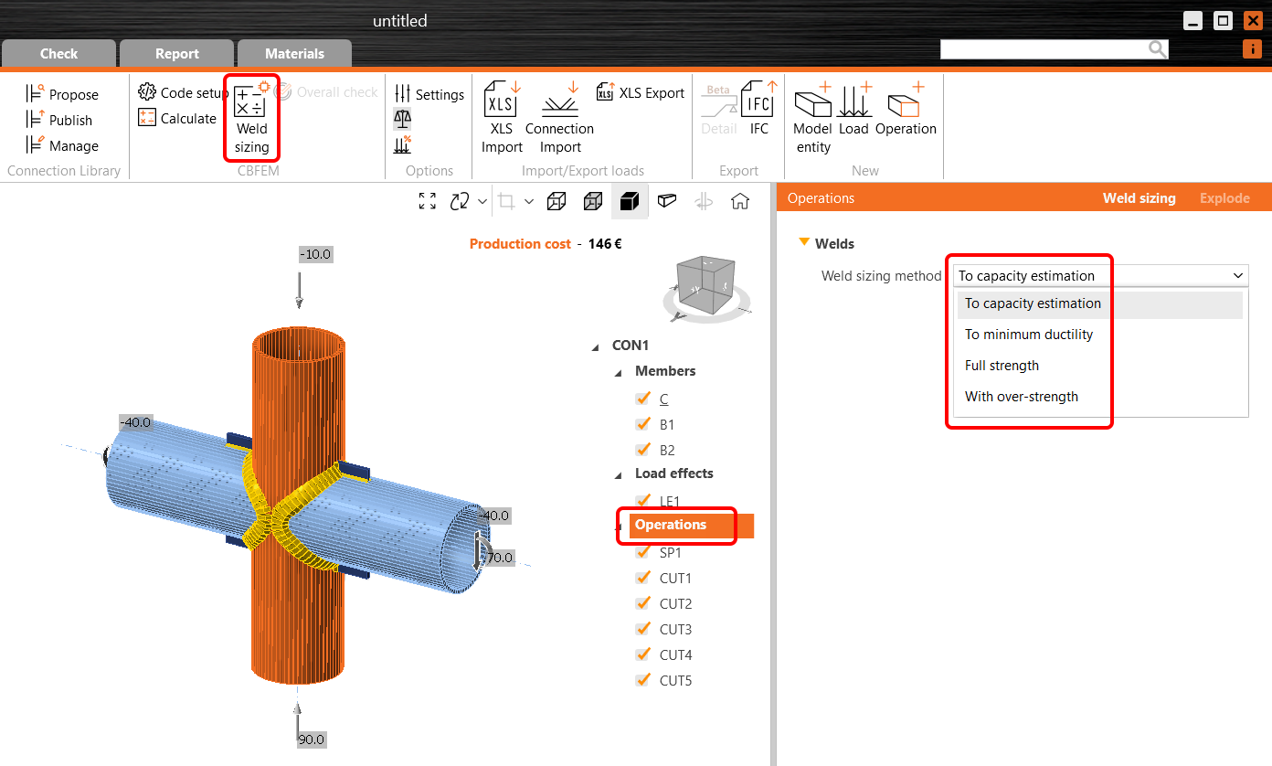
Dans IDEA StatiCa Connection, deux stratégies de dimensionnement des soudures sont disponibles pour tous les utilisateurs :
- à pleine résistance
- avec surrésistance
Pour les utilisateurs de l'Eurocode, deux méthodes supplémentaires sont disponibles :
- par estimation de capacité
- à ductilité minimale
La méthode de dimensionnement des soudures est spécifiée dans le dialogue Opérations.

Lors de l'exécution du dimensionnement des soudures, chaque soudure d'angle du modèle est modifiée selon la méthode de dimensionnement choisie. En général, la taille des soudures augmentera dans cet ordre :
- Par estimation de capacité
- À ductilité minimale
- Pleine résistance
- Avec surrésistance
Les méthodes sont décrites en détail ci-dessous.
Par estimation de capacité
Le dimensionnement des soudures par estimation de capacité fournit automatiquement des dimensions de soudures juste suffisantes pour transmettre les charges définies.
L'estimation de la capacité des soudures est la première application de l'apprentissage automatique dans IDEA StatiCa. Pour l'instant, elle est implémentée uniquement pour l'Eurocode. La résistance de la soudure est déterminée en fonction de l'élément de soudure le plus sollicité. Par conséquent, le taux de travail de la soudure est fortement non linéaire. La résistance sur toute la longueur est estimée par un algorithme d'apprentissage automatique basé sur la distribution des contraintes le long de la soudure.
Le dimensionnement des soudures par estimation de capacité nécessite des résultats. La taille des soudures d'angle est ajustée selon la formule suivante :
\[ a_{new} = a \cdot Ut_c / Ut_{target} \]
où :
- \(a_{new}\) – taille ajustée de la soudure d'angle
- \(a\) – taille précédemment définie de la soudure d'angle
- \(Ut_c\) – estimation de capacité basée sur l'algorithme d'apprentissage automatique, visible dans la vérification des soudures
- \(Ut_{target}\) – taux de travail cible dans Paramètres → Conception → Autodimensionnement → Dimensionnement des soudures
La valeur \(a_{new}\) obtenue est arrondie vers le haut selon Préférences → Unités de l'application → Arrondi des nouvelles entités → Taille de soudure.
Notez que les dimensions des soudures sont limitées par les règles de détaillage, par exemple la taille de la soudure ne peut pas être inférieure à 3 mm (EN 1993-1-8 – 4.5.2). Ces règles de détaillage sont respectées. Gardez également à l'esprit que plusieurs soudures dans IDEA StatiCa sont souvent définies par une seule valeur. Dans ces cas, la taille est définie en fonction de la soudure la plus sollicitée.
Une boucle de calcul est également disponible. Lorsque la méthode de dimensionnement des soudures est définie sur estimation de capacité, elle :
- Dimensionne les soudures d'angle à pleine résistance
- Calcule le modèle
- Dimensionne les soudures d'angle par estimation de capacité
- Calcule le modèle

Les soudures sont alors définies à un taux de travail égal ou inférieur à la cible en un seul clic.
À ductilité minimale
Le dimensionnement des soudures à ductilité minimale fournit automatiquement des assemblages soudés suffisamment résistants pour prévenir les ruptures fragiles. La résistance de la soudure permet la plastification initiale de la plaque, mais en définitive, la soudure se rompt.
L'exigence de ductilité minimale des assemblages soudés est définie dans FprEN 1993-1-8:2023 – 6.9(4). Elle est issue de l'annexe nationale néerlandaise de l'EN 1993-1-8, où le rapport fixe entre la résistance de la soudure et la résistance de la plaque est de 0,8. Elle est également incluse dans les Green books du Royaume-Uni, largement utilisés, notamment dans les chapitres C2 et C3. Cependant, le rapport fixe n'est adapté qu'à la nuance d'acier S355. Dans la deuxième génération de l'Eurocode, cette exigence est étendue à toutes les nuances d'acier.
Cette exigence est vérifiée pour les soudures d'angle double face par :
\[a/t=\frac{\beta_w\gamma_{M2} f_y}{\sqrt{2} f_u \gamma_{M0} } \cdot \min \left \{1.0, 1.1\frac{f_y}{f_u} \right \}\]
où :
- \(a\) – épaisseur de gorge de la soudure
- \(t\) – épaisseur de la plaque assemblée par son bord
- \(\beta_w\) – facteur de corrélation de la soudure
- \(\gamma_{M2}\) – coefficient de sécurité pour les boulons et les soudures ; modifiable dans la configuration normative
- \(f_y\) – limite d'élasticité de la plaque
- \(f_u\) – résistance ultime de la soudure
- \(\gamma_{M0}\) – coefficient de sécurité pour les plaques ; modifiable dans la configuration normative
L'épaisseur de gorge pour une soudure d'angle simple face est deux fois plus grande que celle pour une soudure d'angle double face.
Notez que la méthode est utile pour les soudures chargées transversalement et fonctionne si la plaque est assemblée sur toute sa largeur.
À pleine résistance
Le dimensionnement des soudures à pleine résistance fournit automatiquement des soudures plus résistantes que la plaque assemblée. Dans le calcul, on suppose que les plaques sont chargées en traction et les soudures transversalement, ce qui constitue le cas le plus défavorable pour la résistance et la ductilité des soudures. Cette conception est utile pour éviter les ruptures fragiles des soudures sous chargement statique.
Cette approche est également incluse dans les Green books du Royaume-Uni, largement utilisés, notamment dans le chapitre C1.
Cette exigence est vérifiée pour les soudures d'angle double face par :
\[a/t=\frac{\beta_w\gamma_{M2} f_y}{\sqrt{2} f_u \gamma_{M0} }\]
où :
- \(a\) – épaisseur de gorge de la soudure
- \(t\) – épaisseur de la plaque assemblée par son bord
- \(\beta_w\) – facteur de corrélation de la soudure
- \(\gamma_{M2}\) – coefficient de sécurité pour les boulons et les soudures ; modifiable dans la configuration normative
- \(f_y\) – limite d'élasticité de la plaque
- \(f_u\) – résistance ultime de la soudure
- \(\gamma_{M0}\) – coefficient de sécurité pour les plaques ; modifiable dans la configuration normative
Notez que la méthode est utile pour les soudures chargées transversalement et fonctionne si la plaque est assemblée sur toute sa largeur.
Avec surrésistance
Le dimensionnement des soudures avec surrésistance fournit automatiquement des soudures bien plus résistantes que la plaque assemblée. Le facteur de surrésistance est spécifié dans Paramètres → Conception → Autodimensionnement → Dimensionnement des soudures. La valeur par défaut de 1,4 est tirée de l'EN 1993-1-8 – 6.2.3 (5) pour former une rotule plastique.

Dans le calcul, on suppose que les plaques sont chargées en traction et les soudures transversalement, ce qui constitue le cas le plus défavorable pour la résistance et la ductilité des soudures. Cette conception est utile pour éviter les ruptures fragiles des soudures en conception plastique ou sous chargement cyclique. Notez qu'une grande taille de soudure ne garantit pas automatiquement une ductilité élevée. Au contraire, elle peut entraîner des contraintes résiduelles et des déformations excessives dues au retrait des soudures.
Cette exigence est vérifiée pour les soudures d'angle double face par :
\[a/t=\frac{\beta_w\gamma_{M2} f_y}{\sqrt{2} f_u \gamma_{M0} } \cdot f_{overstrength}\]
où :
- \(a\) – épaisseur de gorge de la soudure
- \(t\) – épaisseur de la plaque assemblée par son bord
- \(\beta_w\) – facteur de corrélation de la soudure
- \(\gamma_{M2}\) – coefficient de sécurité pour les boulons et les soudures ; modifiable dans la configuration normative
- \(f_y\) – limite d'élasticité de la plaque
- \(f_u\) – résistance ultime de la soudure
- \(\gamma_{M0}\) – coefficient de sécurité pour les plaques ; modifiable dans la configuration normative
- \(f_{overstrength}\) – facteur de surrésistance spécifié dans Paramètres → Conception → Autodimensionnement → Dimensionnement des soudures
Notez que la méthode est utile pour les soudures chargées transversalement et fonctionne si la plaque est assemblée sur toute sa largeur.