Burgers’ Zoo Mangrove, Arnhem, The Netherlands
Project data
Location - Antoon van Hooffplein 1, Arnhem
Order - Koninklijke Burgers' Zoo, Arnhem
Architecture - Koninklijke Burgers' Zoo / Sijven Eindhoven, Arnhem
Structural Design - ABT, Velp
Structural Detail Design - Staalbouwkundig Adviesburo Van Odenhoven
Performance - P&H Adviseurs Construction & Real Estate (construction management and supervision), Veldhoven
Steel construction - Moeskops Steel Construction, Bergeijk

General project description
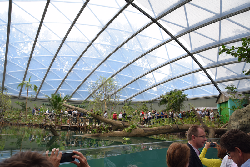
Worldwide, large areas of mangrove are disappearing although they have an essential function for nature. Burgers' Zoo wants to create awareness among visitors and has built the largest covered mangrove in the world in Arnhem. The mangrove is based on the mangrove forests of the Central American country of Belize. Upon entering Burgers' Mangrove, the journey begins crossing a steel bridge over the manatee basin (100 m3). Then the route continues on a platform through the mangrove forest. Few plant species can survive in this extremely salty climate, where different conditions arise at ebb and flow. Ahead, direct visual contact with the Caribbean sea cows is created thanks to a curved acrylic window 12 m long and 1.8 m high. Burgers' Mangrove is covered by a 60 m steel dome construction. The basin of the Caribbean manatees is filled with 1 million liters of water.

Description of steel construction and/or use of steel
Designing is an integral process in which choices are weighed. For the mangrove hall, the biggest consideration during the design was a careful choice between a surface as possible for the presentation of the eco-display within an optimal building shape and, on the other hand, a volume as large as possible, whereby the construction costs are controlled by the smallest possible facade/roof surface. In addition, the construction had to be realized on the outside, just like with Burgers 'Bush and Burgers' Desert. The chosen arc-shaped roof construction fits in well with the above-mentioned requirements. The construction is highest in the middle, which makes the experience of the eco display optimal and makes tree growth possible. At the lower parts of the dome, there is sufficient remaining height to use the space functionally and the surface of the vertical facade is kept to a minimum.
The dome structure is designed in steel, which is remarkable in itself, as many of these structures are designed in wood. Steel was chosen because this eco-display requires a lot of daylight. A timber construction would greatly reduce the incidence of light due to its large profile dimensions, creating a lot of shadows.
Steel appears to be much better suited for the required high tensile forces in the bottom ring.
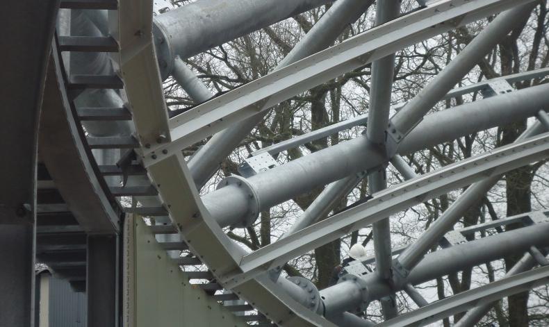
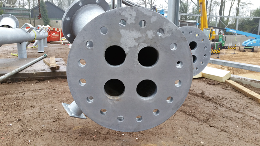
The dome is spanned in one direction by steel pipes with a diameter of 323 mm and a wall thickness of 8 mm. The tubes do not run parallel to each other due to the double curvature of the dome, but generally, they are about 4 meters apart. The largest span consists of five prefabricated pieces with an average length of 13 meters; the smaller spans consist of fewer pieces. The parts are coupled with flange connections with every ten bolts. An important detail is that the flanges in the heart have so-called dezincification holes to prevent deterioration of the hot-dip galvanized steel. This is because the entire construction is exposed to outside conditions because the actual roof sealing hangs underneath.
Between the main pipes, there are diagonal strut connections, consisting of pipes with a diameter of 193 mm and a wall thickness of 8 mm. The struts are connected to the main pipes with fork joints. The plates of these connections are prefabricated to the main and strut pipes. This required precise dimensions and work, because each fork joint is at a different angle due to the double curvature of the dome. During the assembly of the main pipes and the struts, the whole was temporarily supported by three auxiliary structures. This was necessary because the dome only gains its strength when the dome construction is actually closed. The dome is built up step by step. After the dome was closed, the auxiliary structure was removed.
The bottom ring absorbs all forces from the dome. It is composed of the same tubes as the main girders: tubes with a diameter of 323 mm and a wall thickness of 8 mm. This beam is also made up of prefabricated parts, which are connected with welded flanges of 40 mm thick, for extra safety. The main tubes of the dome are flanged to the bottom ring. Short pieces of the tube are welded to this with a bottle plate on the head. For these coupling pieces, tight dimensions and accuracy were also required, because the position of these connections was again different for each main tube due to the curvature of the dome.
The bottom ring is supported on its own by steel columns, HEA 240 profiles, which, as already indicated, are spaced between 4.50 and 5.00 m. The columns have different lengths due to the change of the ground level. Here and there a wind bracing has been applied between the columns. All columns are braced during the assembly and during the assembly of the dome construction, the draw beam is every two columns.
Special constructive cleverness / details
At the edge of the dome, the net structure comes together in a ring. This ring is supported by pendulum columns and diagonal bracing has been applied between the columns.
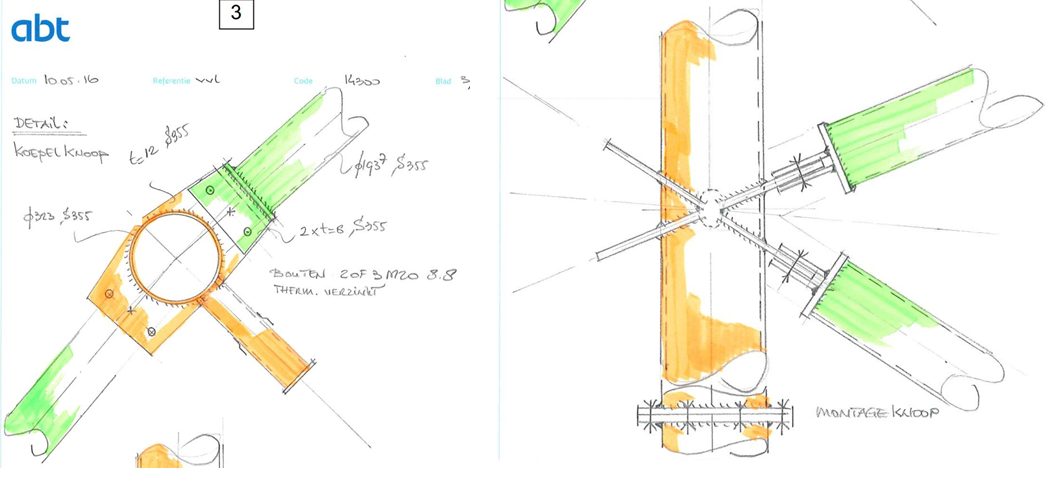
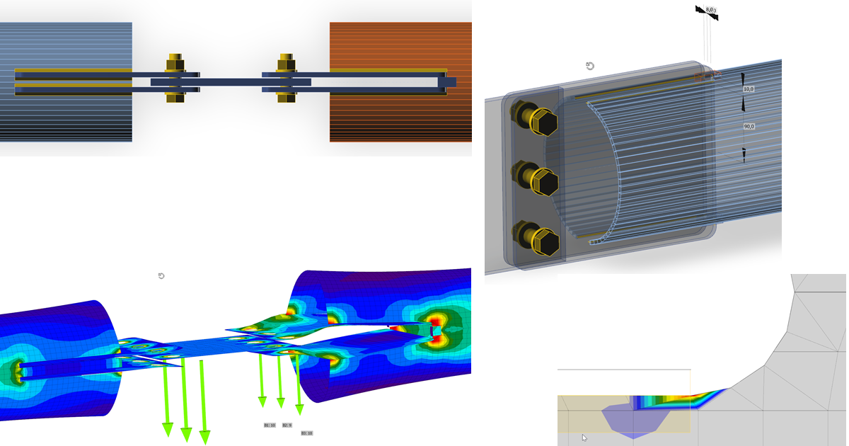
The segmentation bottom ring has a dimension Ø 323,9 x 8 S355J2H, conditions demanded by the client were as follows:
- The connection needs to withstand normal force Nc,Rd = 2818 kN
- Thermal galvanized construction needs ‘sinkholes’ ≥ 30% of the cross-section
- No steel connected unwelded allowed, not even internally (both sides fillet welds or butt weld)
- Outside of construction is not allowed the accumulation of dirt, leaves, etc.
- Connections for assembly only with bolts (no welding on site)
The final solution of the joints was computed using IDEA StatiCa Connection.

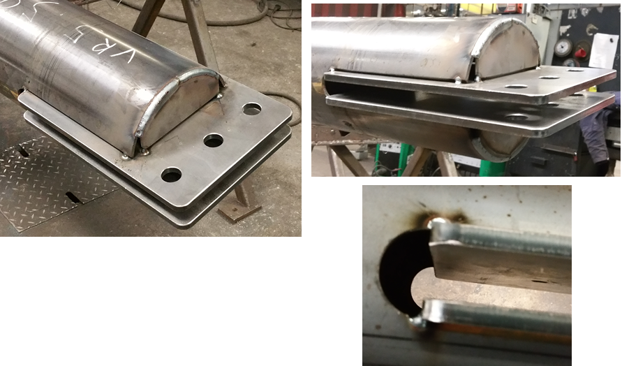
For the design of the diagonal bracing the challenge was following:
- such structure is very sensitive to fabrication tolerances
- the holes for galvanizing weaken critical cross-section
- 1 lip only weldable to 1 side
By using IDEA StatiCa Connection could be solved all these issues with perfectly welded plates and without holes for galvanizing.

Conclusion
Said by the words of the engineering team: "Designing in Idea StatiCa Connection is like using the "LEGO" bricks for the Detailer or Structural engineer."
Photo credits: ABT B.V.