
Connection tutorial - Tubular 3D frame (AISC)
1 New project
Start with launching the IDEA StatiCa Connection. Create a new project by selecting the template closest to the required design, fill the name and the description of the project. After choosing the required properties, confirm by Create project.

Since you work under the AISC code, set the imperial units (see How to change the system of units).
2 Geometry
Start with a modification of the joint geometry. Select member CH and click the "+" icon to open the Cross-Section Navigator. Choose the Circular hollow section profile and select HSS12.75X.500 cross-section along with the corresponding library.
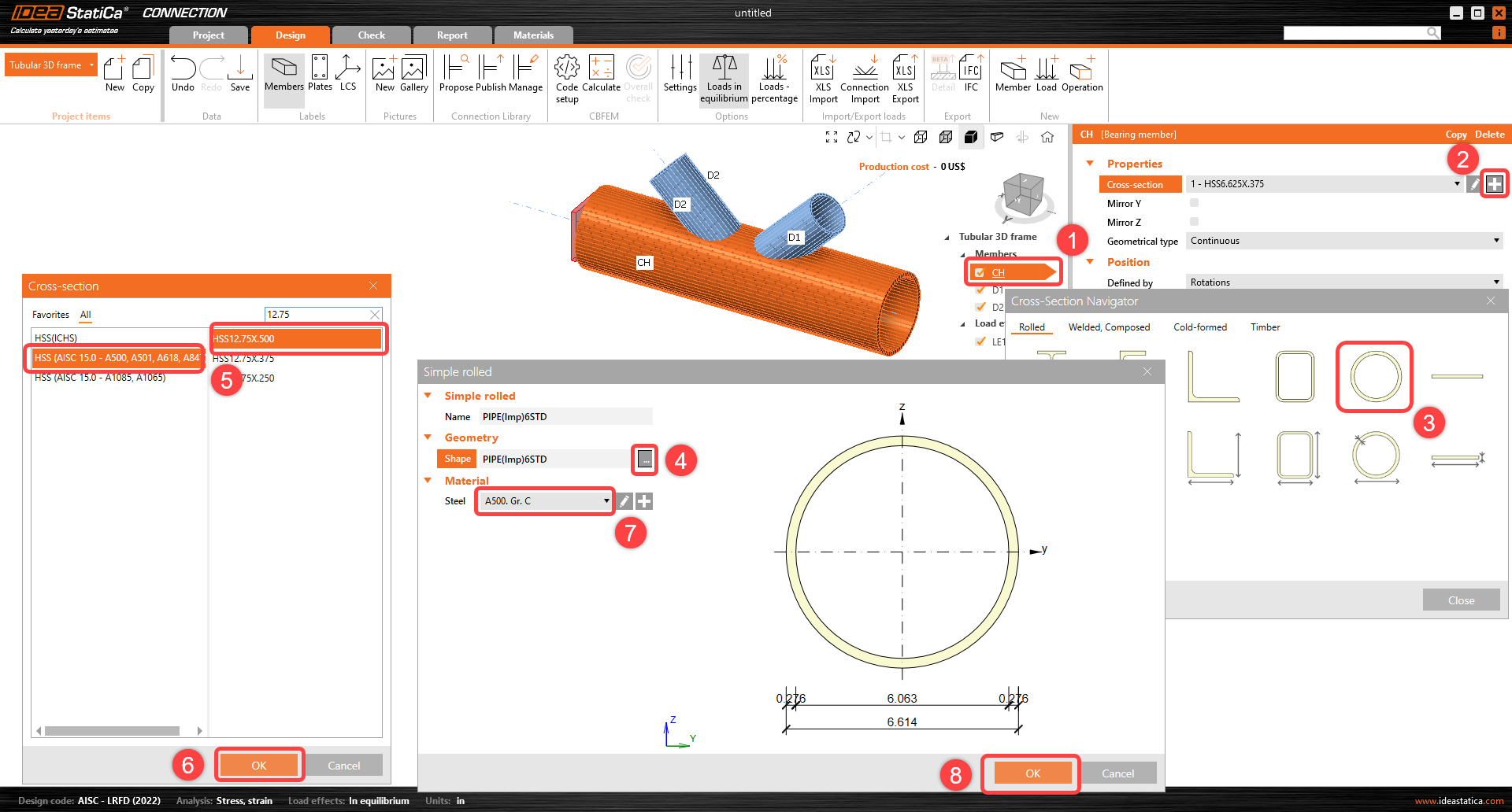
The member CH properties must be adjusted, follow the image below.

Take advantage of the prepared member to copy its properties, under the tree of the entities, right-click member CH and select Copy command.
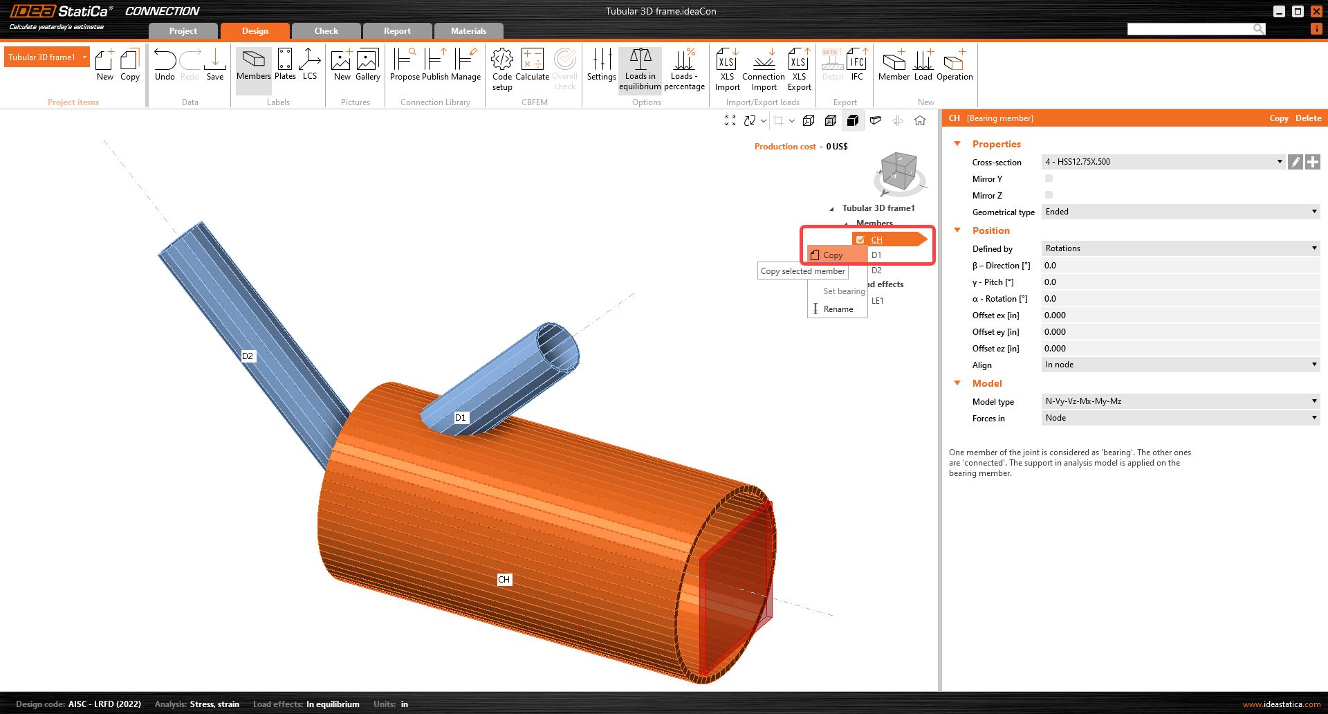
Adjust the properties of member M4 following the image below.

Proceed with the change of cross-section on the diagonal member D1. In this case, the cross-section HSS6.625X0.375 has already been defined in the template. Choose the first cross-section from the dropdown menu and adjust the properties as shown below.

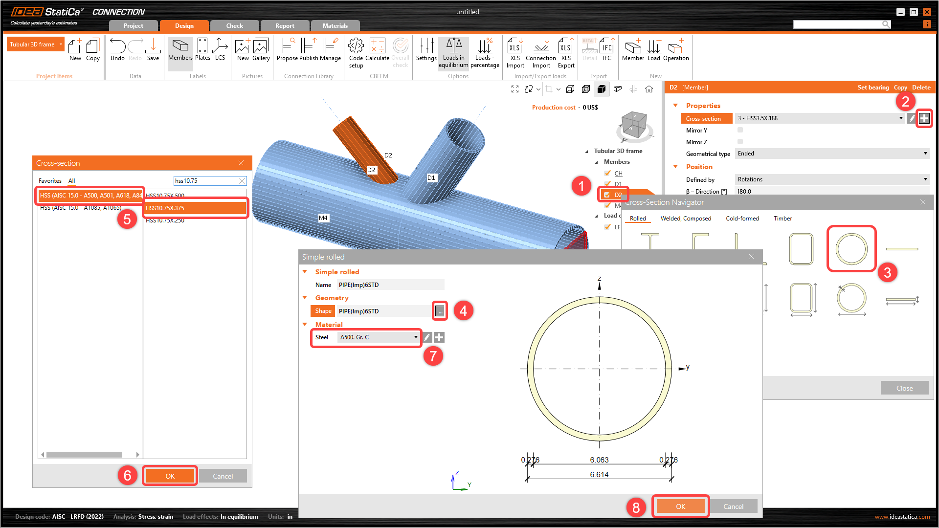
Proceed to the second diagonal member D2 and change the properties following the image below. The new cross-section is HSS10.75X.375.
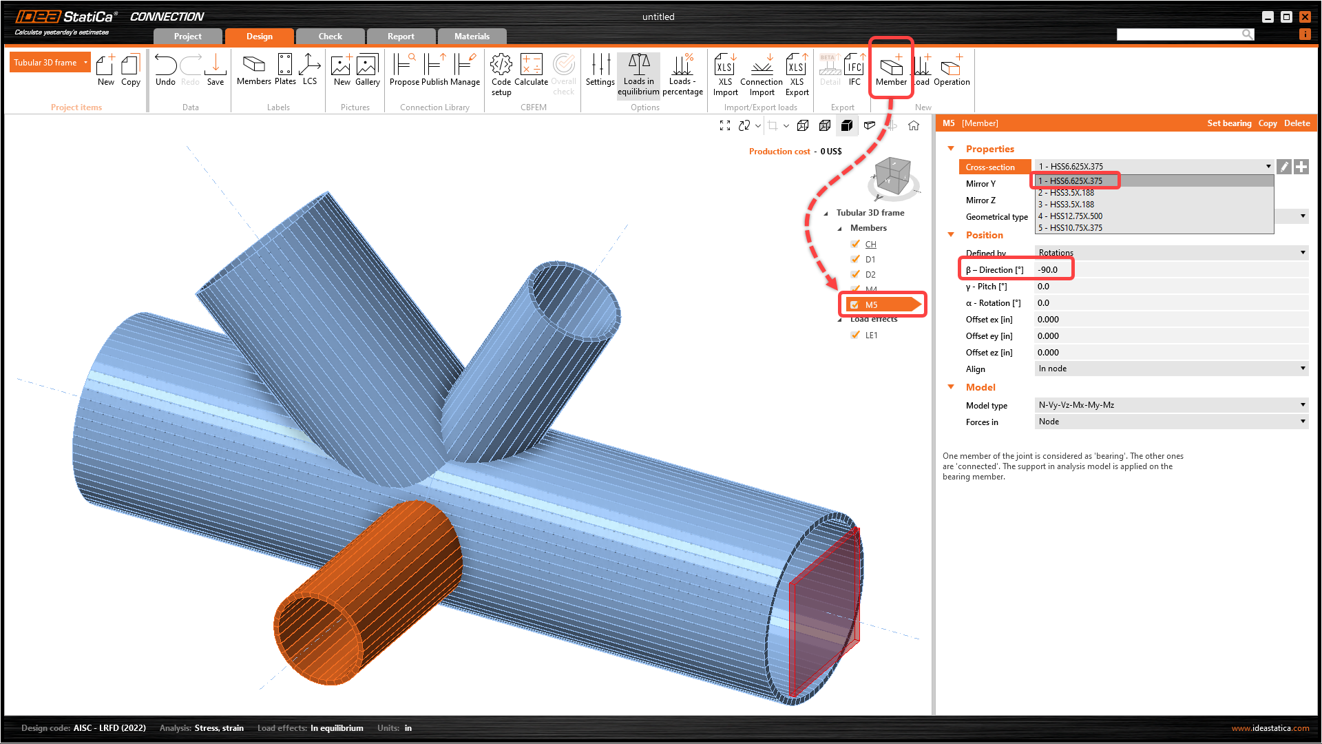
Now you have to add another member, click the Member option at the top ribbon. Change the direction and cross-section for the new member as shown in the image below.
3 Load effects
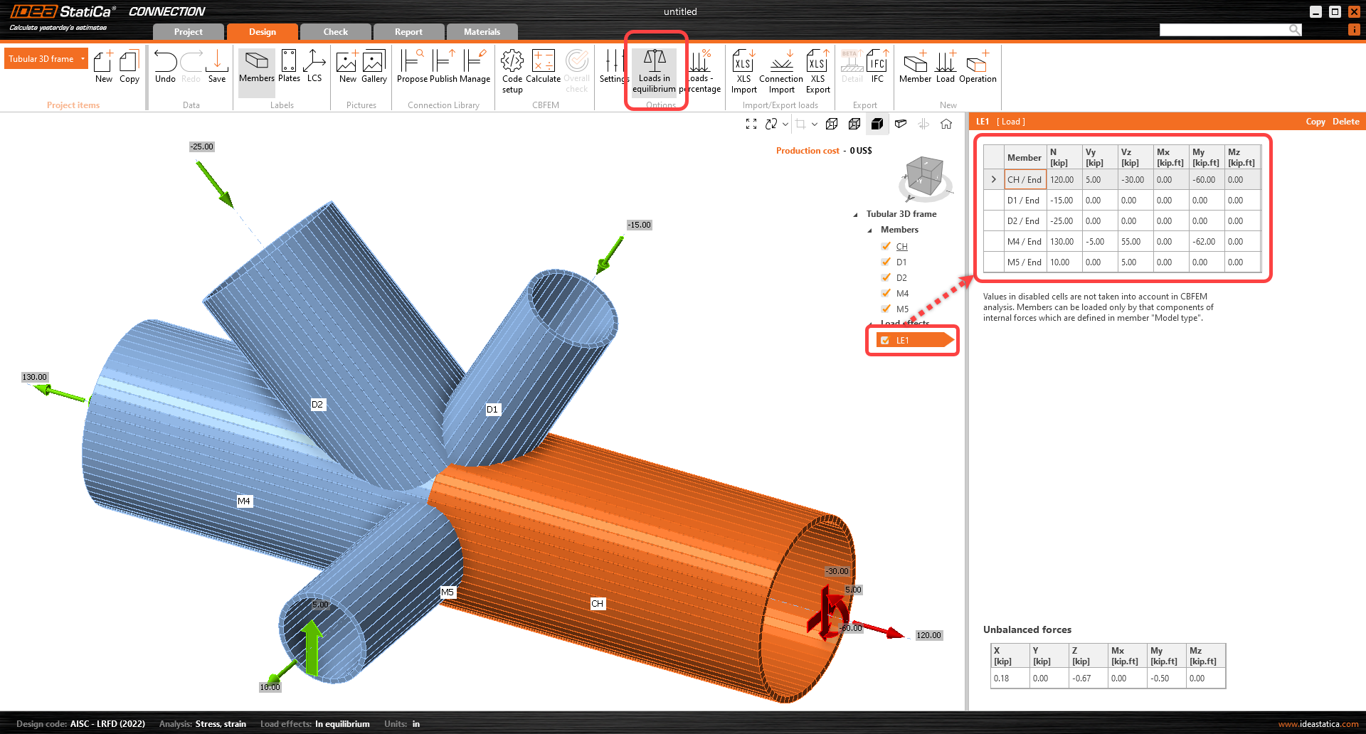
You can continue with the Load effects. One load effect was automatically added by the wizard. You will input all internal forces into the table. You should not forget to turn on the Loads in equilibrium command in the top ribbon.
4 Design
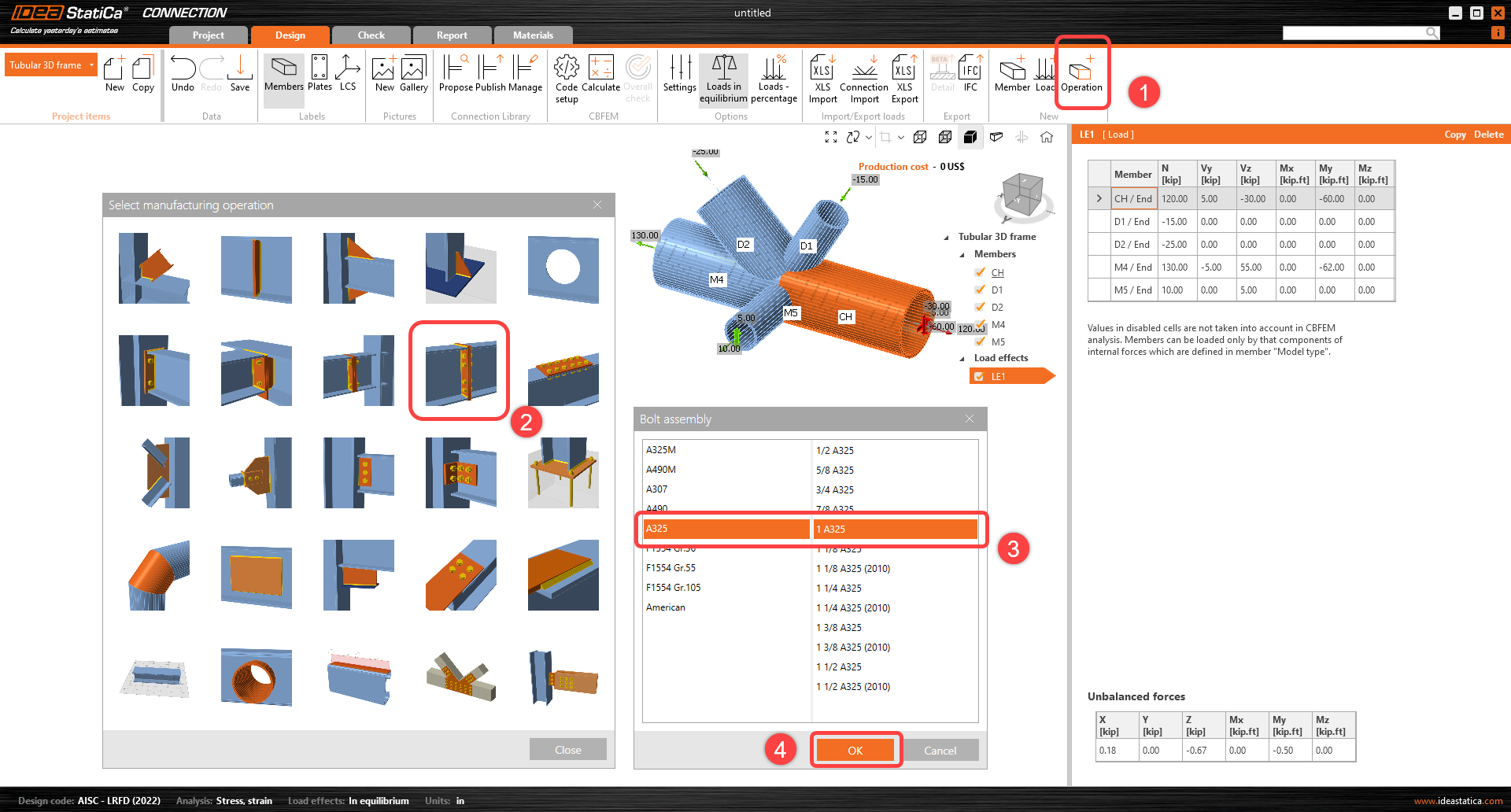
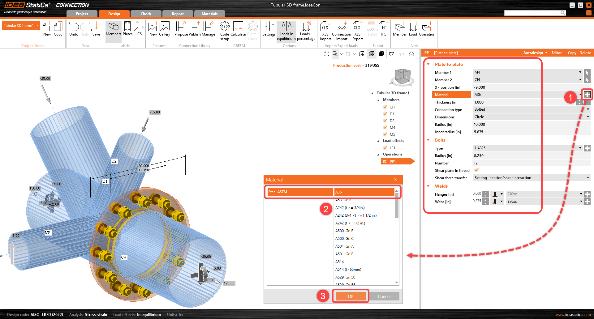
You have to define the right manufacturing operation. Start with selecting the Operation feature at the top ribbon. The Manufacturing operations window will open with all available operations. Select the Plate to plate operation and adjust the properties as shown in the following image.
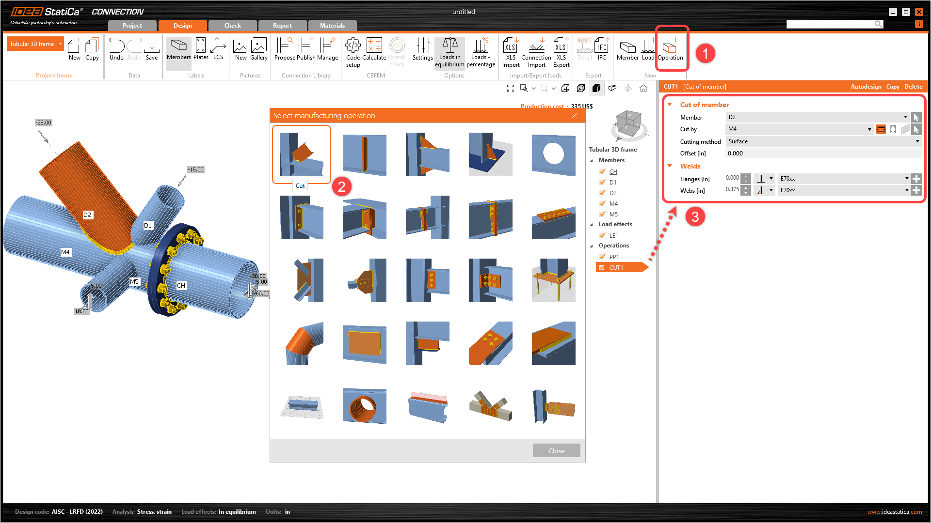
Now, connect the other members by the Cut manufacturing operations. Add a new operation through the Operation feature at the top ribbon to cut member D2. Change the properties of the operation CUT1 following the image below.
Take advantage of the already defined operation, right-click on operation CUT1 and select Copy command.

Change the properties of CUT2 operation following the image below.

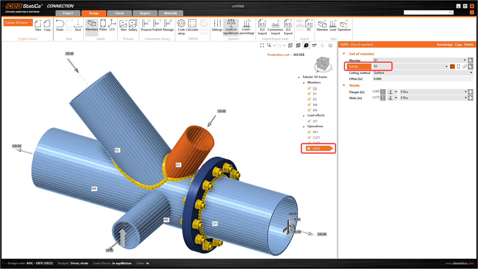
Copy the CUT2 manufacturing operation and change the properties of the CUT3 manufacturing operation following the image below.
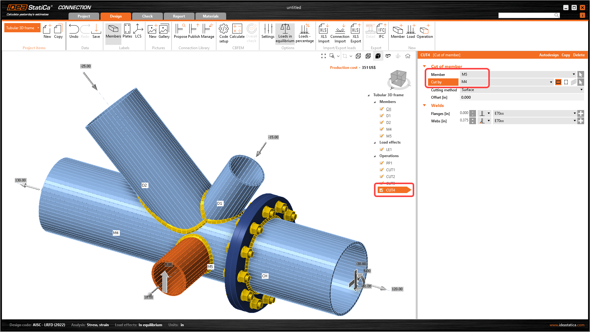
The last step in the design of the joint is the last copy of the CUT3. Change the properties of the CUT4 following the image below.
5 Calculation and Check
You can calculate the analysis right in the Design tab by the Calculate command.

After a while, the results summary will appear in the left top corner of the 3D scene, and the Overall check model view is set. You can quickly fine-tune the model in case we are not satisfied.

You will choose the Check tab and turn on the Equivalent stress, Mesh, and Deformed model view. You can explore the detailed results for the Bolts also, let’s expand the results for the bolt B7.

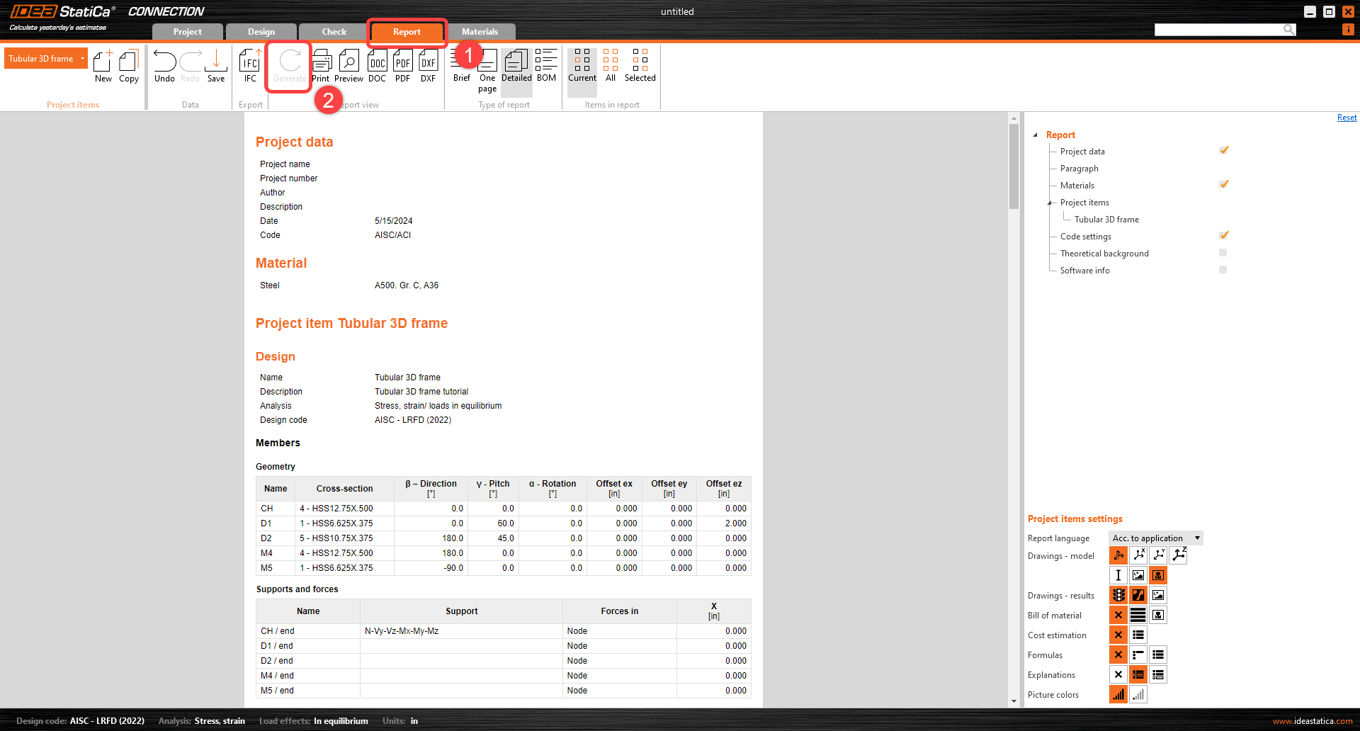
6 Report
At last, go to the tab Report. IDEA StatiCa offers a fully customizable report to print out or save in an editable format.
You have designed, optimized, and code-checked a structural steel joint according to AISC.