Verificarea componentelor îmbinării metalice (EN)
Metoda CBFEM combină avantajele Metodei Elementelor Finite (MEF) generale și ale Metodei Componentelor (MC) standard. Tensiunile și forțele interioare calculate pe modelul CBFEM precis sunt utilizate în verificarea tuturor componentelor.
Componentele individuale sunt verificate conform Eurocode EN 1993-1-8.
Verificarea conform codului a plăcilor din oțel (EN)
Tensiunea echivalentă rezultantă (Huber-Mises-Hencky – HMH, von Mises) și deformația principală plastică sunt calculate pe plăci. Modelul de material elasto-plastic este utilizat pentru plăcile din oțel. Se efectuează o verificare a deformației plastice echivalente. Valoarea limită de 5 % este sugerată în Eurocode (EN 1993-1-5, anexa C, par. C8, nota 1); această valoare poate fi modificată de utilizator în configurarea codului.
Elementul de placă este împărțit pe grosimea sa în cinci straturi de elemente finite de tip cochilie, iar comportamentul elastic/plastic este investigat în fiecare strat separat. Rezumatul rezultatelor listează verificarea cea mai critică din toate cele cinci straturi.
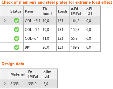
Metoda CBFEM poate furniza tensiuni mai mari decât limita de curgere. Motivul este ușoara înclinare a ramului plastic al diagramei efort-deformație, care este utilizată în analiză pentru a îmbunătăți stabilitatea calculului de interacțiune. Aceasta nu reprezintă o problemă pentru proiectarea practică. La încărcări mai mari, deformația plastică echivalentă crește, iar îmbinarea cedează la depășirea limitei de deformație plastică.
Verificarea conform codului a sudurilor (EN)
Sudurile de colț sunt verificate conform EN 1993-1-8. Rezistența sudurilor cap la cap este considerată egală cu cea a metalului de bază și nu este verificată.
Suduri de colț
Rezistență de calcul
Redistribuirea plastică în suduri este utilizată pentru a evita automat singularitățile de tensiune în elementele de sudură și pentru a redistribui tensiunea pe lungimea sudurii. Rezistența sudurii corespunde aproximativ calculului manual, iar tensiunea este distribuită corect pentru cazuri complexe, cum ar fi sudarea pe o talpă nerigidizată (EN 1993-1-8 – Cl. 4.10). Tensiunea în secțiunea gâtului unui suduri de colț este determinată conform EN 1993-1-8 Cl. 4.5.3. Tensiunile sunt calculate din tensiunile din elementul de sudură. Momentul încovoietor în jurul axei longitudinale a sudurii nu este luat în considerare.
\[ \sigma_{w,Ed}=\sqrt{\sigma_{\perp}^2 + 3 \left ( \tau_{\perp}^2 + \tau_{\parallel}^2 \right )} \]
\[ \sigma_{w,Rd} = \frac{f_u}{\beta_w \gamma_{M2}} \]
Grad de utilizare al sudurii
\[ U_t = \max \left\{ \frac{\sigma_{{w,Ed}}}{\sigma_{w,Rd}}, \frac{\sigma_{\perp}}{0.9 f_u / {\gamma_{M2}}} \right\} \]
unde:
- σw,Ed – tensiunea echivalentă în sudură
- σw,Rd – rezistența sudurii
- βw – factor de corelație (EN 1993-1-8 – Tabelul 4.1)
- fu – rezistența la rupere, aleasă ca valoarea minimă dintre cele două materiale de bază îmbinate sau conform materialului ales de utilizator
- γM2 – factor de siguranță (EN 1993-1-8 – Tabelul 2.1; editabil în Configurarea codului)
- σ┴, τ┴, τ‖ – tensiuni în sudură conform figurii de mai jos:
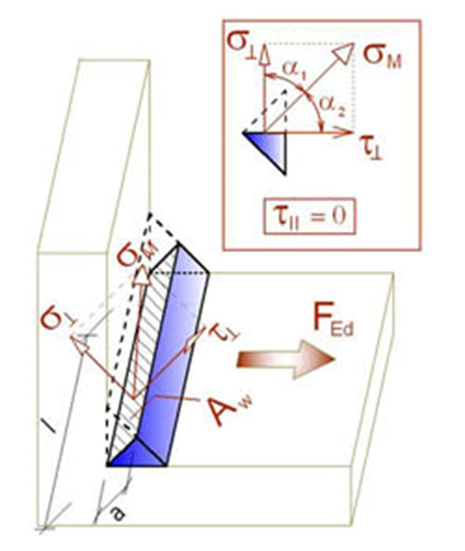
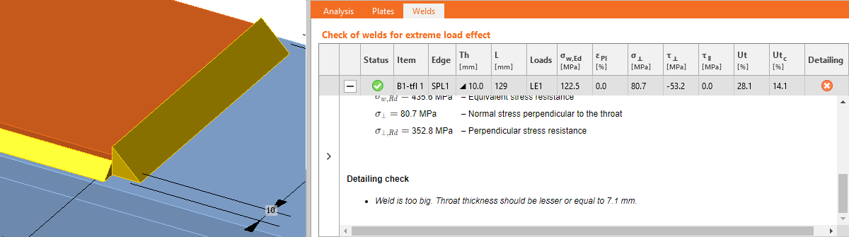
Toate valorile necesare pentru verificare sunt afișate în tabele. Ut reprezintă gradul de utilizare al elementului cel mai solicitat. Deoarece se utilizează redistribuirea plastică a tensiunii în sudură, acesta este gradul de utilizare determinant. Utc furnizează informații despre gradul de utilizare pe lungimea sudurii. Reprezintă raportul dintre tensiunea reală din toate elementele sudurii și rezistența de calcul a tensiunii pe întreaga lungime a sudurii.
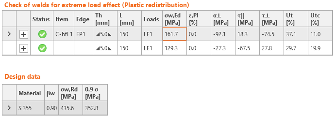
Diagrama tensiunii echivalente în sudură prezintă următoarea tensiune:
\[ \sigma = \max \left \{ \frac{\sigma_{\perp}}{0.9 \beta_w}, \, \sqrt{\sigma_{\perp}^2 + 3 \tau_{\perp}^2 + 3 \tau_{\parallel}^2} \right \} \]
Suduri cap la cap
Sudurile pot fi specificate ca suduri cap la cap. Pentru sudurile cap la cap se consideră penetrare completă a îmbinării, prin urmare acestea nu sunt verificate.
Detaliere
Grosimea minimă a plăcilor pentru îmbinările sudate este verificată conform EN 1993-1-8 – 4.1(1):
- Pentru secțiunile tubulare din oțel, grosimea plăcii trebuie să fie de cel puțin 2,5 mm
- Pentru celelalte plăci, grosimea plăcii trebuie să fie de cel puțin 4 mm
Grosimea maximă a gâtului sudurii de colț este verificată pentru plăci paralele. Se emite o eroare, deoarece o astfel de sudură nu este realizabilă din cauza constrângerilor geometrice.
Grosimea minimă a gâtului sudurii de colț trebuie să fie de cel puțin 3 mm conform EN 1993-1-8 – 4.5.2(2). Se emite o eroare când această cerință nu este îndeplinită.
Se emite un avertisment când grosimea gâtului sudurii este mai mică decât cerința din DIN EN 1993-1-8 – NA la 4.5.2:
\[a \le \sqrt{t_{max}}-0.5\]
unde:
- \(a\) – grosimea gâtului sudurii
- \(t_{max}\) – grosimea plăcii mai groase îmbinate
- unitățile trebuie să fie în [mm]
Se emite o informare când grosimea gâtului sudurii este mai mică decât cerința privind ductilitatea minimă a îmbinărilor sudate din FprEN 1993-1-8:2023 – 6.9(4). Această cerință este verificată pentru sudurile de colț pe ambele fețe prin:
\[a/t=\frac{\beta_w\gamma_{M2} f_y}{\sqrt{2} f_u \gamma_{M0} } \cdot \min \left \{1.0, 1.1\frac{f_y}{f_u} \right \}\]
unde:
- \(a\) – grosimea gâtului sudurii
- \(t\) – grosimea plăcii îmbinate prin margine
- \(\beta_w\) – factor de corelație al sudurii
- \(\gamma_{M2}\) – factor de siguranță pentru șuruburi și suduri; editabil în Configurarea codului
- \(f_y\) – limita de curgere a plăcii
- \(f_u\) – rezistența la rupere a sudurii
- \(\gamma_{M0}\) – factor de siguranță pentru plăci; editabil în Configurarea codului
Grosimea gâtului sudurii de colț pe o singură față este de două ori mai mare decât cea pentru sudura de colț pe ambele fețe.
Verificarea conform codului a șuruburilor și șuruburilor pretensionate (EN)
Șuruburi
Rigiditatea inițială și rezistența de calcul a șuruburilor la forfecare sunt modelate în CBFEM conform Cl. 3.6 și 6.3.2 din EN 1993-1-8. Arcul care reprezintă presiunea pe gaură și întinderea are un comportament forță-deformație biliniar, cu rigiditate inițială și rezistență de calcul conform Cl. 3.6 și 6.3.2 din EN 1993-1-8.
Rezistența de calcul la întindere a șurubului (EN 1993-1-8 – Tabelul 3.4):
\[ F_{t,Rd}=0.9 f_{ub} A_s / \gamma_{M2} \]
Rezistența de calcul la forfecare prin poansonare a capului șurubului sau a piuliței (EN 1993-1-8 – Tabelul 3.4):
\[ B_{p,Rd} = 0.6 \pi d_m t_p f_u / \gamma_{M2} \]
Rezistența de calcul la forfecare pe un plan de forfecare (EN 1993-1-8 – Tabelul 3.4):
\[ F_{v,Rd} = \alpha_v f_{ub} A_s / \gamma_{M2} \]
Rezistența de calcul la forfecare poate fi înmulțită cu factorul de reducere βp dacă există garnituri de umplutură (EN 1993-1-8 – Cl. 3.6.1. (12)), iar această opțiune este selectată în configurarea codului.
Rezistența de calcul la presiune pe gaură a plăcii (EN 1993-1-8 – Tabelul 3.4):
\( F_{b,Rd} = k_1 \alpha_b f_u d t / \gamma_{M2} \) pentru găuri standard
\( F_{b,Rd} = 0.6 k_1 \alpha_b f_u d t / \gamma_{M2} \) pentru găuri ovale
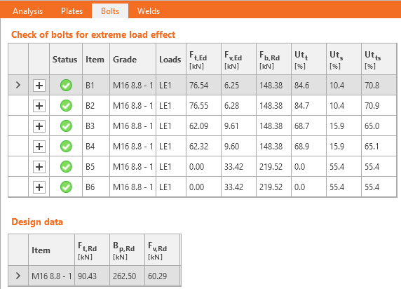
Grad de utilizare la întindere [%]:
\[ Ut_t = \frac{F_{t,Ed}}{\min (F_{t,Rd},\, B_{p,Rd})} \]
Grad de utilizare la forfecare [%]:
\[ Ut_s = \frac{F_{v,Ed}}{\min (F_{v,Rd},\, F_{b,Rd})} \]
Interacțiunea forfecare-întindere [%]:
\[ Ut_{ts}=\frac{F_{v,Ed}}{F_{v,Rd}}+\frac{F_{t,Ed}}{1.4 F_{t,Rd}} \]
unde:
- As – aria secțiunii transversale a tijei filetate a șurubului
- fub – rezistența ultimă la întindere a șurubului
- dm – media dimensiunilor pe vârfuri și pe fețe ale capului șurubului sau ale piuliței, luând valoarea mai mică
- d – diametrul șurubului
- tp – grosimea plăcii sub capul șurubului/piuliță
- fu – rezistența ultimă a oțelului
- αv = 0.6 pentru clasele 4.6, 5.6, 8.8 și 0.5 pentru clasele 4.8, 5.8, 6.8, 10.9
- \( k_1 = \min \left \{2.8 \frac{e_2}{d_0}-1.7, \, 1.4 \frac{p_2}{d_0}-1.7, \, 2.5 \right \} \) – factor din Tabelul 3.4
- \(\alpha_b = 1.0\) dacă verificarea la presiune pe gaură cu \(\alpha_b\) este dezactivată în configurarea codului; dacă verificarea este activată, valoarea lui αb se determină conform EN 1993-1-8 – Tabelul 3.4: \( \alpha_b = \min \left \{ \alpha_d, \, \frac{f_{ub}}{f_u}, \, 1.0 \right \} \)
- \(\alpha_d = \min \left \{ \frac{e_1}{3 d_0}, \, \frac{p_1}{3 d_0}-\frac{1}{4} \right \} \)
- e1, e2 – distanțele la margine în direcția forței și perpendicular pe forță
- p1, p2 – pasul șuruburilor în direcția forței și perpendicular pe forță
- Ft,Ed – forța de întindere de calcul în șurub
- Fv,Ed – forța de forfecare de calcul în șurub
- γM2 – factor de siguranță (EN 1993-1-8 – Tabelul 2.1; editabil în configurarea codului)
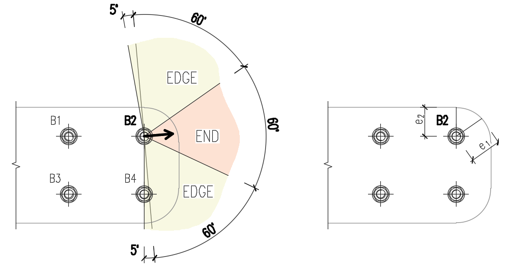
Distanțele la margine utilizate pentru rezistența la presiune pe gaură a șuruburilor trebuie să fie relevante pentru geometrii generale ale plăcilor, plăci cu deschideri, decupaje etc.
Algoritmul citește direcția reală a vectorului forței de forfecare rezultante într-un șurub dat și calculează apoi distanțele necesare pentru verificarea la presiune pe gaură.
Distanțele la capăt (e1) și la margine (e2) se determină prin împărțirea conturului plăcii în trei segmente. „Segmentul de capăt" este indicat printr-un interval de 60° în direcția vectorului forței. „Segmentele de margine" sunt definite prin două intervale de 65° perpendiculare pe vectorul forței. Cea mai scurtă distanță dintre un șurub și o margine în segmentul relevant este luată ca distanță la capăt sau la margine.
Algoritmul evaluează toate plăcile conectate de șurub — plăcile de îmbinare (de ex., o placă de eclisă), plăcile elementului (de ex., o talpă superioară) — și se utilizează cea mai scurtă distanță.
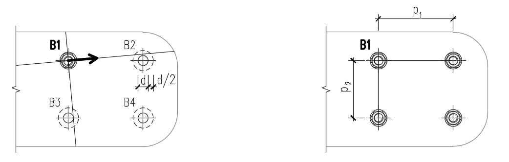
Distanțele dintre găurile șuruburilor (p1; p2) se determină prin mărirea virtuală a găurilor șuruburilor înconjurătoare cu jumătate din diametrul lor, trasând apoi două linii în direcția și perpendicular pe vectorul forței de forfecare. Când aceste linii intersectează găurile virtual mărite ale șuruburilor, distanțele până la aceste șuruburi sunt considerate ca p1 și p2 în calcul.
Dacă liniile nu intersectează cel mai apropiat șurub vizual (chiar dacă linia trece aproape de șurub), acest șurub este neglijat. Dacă liniile nu intersectează niciun șurub, se utilizează o valoare infinită.
Șuruburi care conectează plăci cu pereți subțiri
Pentru șuruburile care conectează plăci mai subțiri de 3 mm, se utilizează prevederile EN 1993-1-3, Tabelul 8.4.
Rezistența la presiune pe gaură:
\[F_{b,Rd}=2.5\cdot \alpha_b \cdot k_t \cdot f_u \cdot d \cdot t /\gamma_{M2}\]
unde:
- \( \alpha_b=\min \left \{ 1.0, e_1/(3d) \right \} \)
- \(k_t = (0.8 t+1.5)/2.5 \) pentru 0.75 mm \(\le t \le\) 1.25 mm; \( k_t=1.0 \) pentru \(t>1.25\) mm
- \(f_u\) – rezistența ultimă a plăcii conectate
- \(d\) – diametrul șurubului
- \(t\) – grosimea plăcii conectate
- \(\gamma_{M2}\) – factor parțial de siguranță pentru îmbinări, editabil în configurarea codului; implicit \(\gamma_{M2}=1.25\)
Rezistența la forfecare, rezistența la întindere, interacțiunea întindere-forfecare și rezistența la forfecare prin poansonare se determină conform EN 1993-1-8 – în același mod ca pentru șuruburile care conectează plăci cu grosime mai mare de 3 mm.
Domeniu de valabilitate:
\[e_1 \ge 1.0 d_0 \]
\[p_1 \ge 3 d_0 \]
\[e_2 \ge 1.5 d_0 \]
\[p_2 \ge 3 d_0 \]
\[ f_u \le 550 \textrm{ MPa} \]
\[3 \textrm{ mm} > t \ge 0.75 \textrm{ mm} \]
Dimensiunea minimă a șurubului: M6 – verificat ca \(d \ge 6\) mm
Clase de rezistență ale șuruburilor: 4.6 – 10.9 – verificat ca \(f_u \le 1000\) MPa
Șuruburile vor fi marcate ca necorespunzătoare dacă se află în afara domeniului de valabilitate.
Șuruburi pretensionate
Rezistența de calcul la alunecare pe șurub de clasa 8.8 sau 10.9 (EN 1993-1-8, Cl. 3.9 – Ecuația 3.8):
\[ F_{s,Rd} =\frac{k_s n \mu (F_{p,C} - 0.8 F_{t,Ed})}{\gamma_{M3}} \]
Forța de pretensionare (EN 1993-1-8 – Ecuația 3.7)
Fp,C = 0.7 fub As
Factorul forței de pretensionare 0.7 poate fi modificat în configurarea codului.
Grad de utilizare [%]:
\[ Ut_s = \frac{V}{F_{s,Rd}} \]
unde:
- As – aria secțiunii transversale a tijei filetate a șurubului
- fub – rezistența ultimă la întindere
- ks – coeficient (EN 1993-1-8 – Tabelul 3.6; ks = 1 pentru găuri rotunde normale, ks = 0.63 pentru găuri ovale)
- μ – factorul de alunecare editabil în configurarea codului (EN 1993-1-8 – Tabelul 3.7)
- n – numărul suprafețelor de frecare. Verificarea se calculează separat pentru fiecare suprafață de frecare
- γM3 – factor de siguranță (EN 1993-1-8 – Tabelul 2.1; editabil în configurarea codului – valorile recomandate sunt 1.25 pentru starea limită ultimă și 1.1 pentru starea limită de serviciu)
- V – forța de forfecare de calcul în șurub
- Ft,Ed – forța de întindere de calcul în șurub
Dacă alunecarea șuruburilor pretensionate este verificată pentru starea limită de serviciu, acestea trebuie ulterior comutate la „presiune pe gaură – interacțiune întindere/forfecare" și verificate pentru starea limită ultimă.
Proiectare la foc
Se presupune că șuruburile pretensionate alunecă, astfel încât verificările pentru șuruburile cu presiune pe gaură și pentru șuruburile pretensionate sunt identice.
Verificările la foc și la temperatura ambiantă sunt efectuate ambele, iar minimul este selectat ca rezistență de calcul la acțiunea de proiectare.
La temperaturi ridicate, șuruburile sunt verificate conform EN 1993-1-2, Anexa D. Se remarcă faptul că aria redusă de filet este întotdeauna utilizată în verificarea la forfecare conform D1.1.1.
Detaliere
Verificările de detaliere ale șuruburilor se efectuează dacă opțiunea este selectată în configurarea codului. Se verifică dimensiunile de la centrul șurubului la marginile plăcii și dintre șuruburi. Distanța la margine e = 1.2 și distanța dintre șuruburi p = 2.2 sunt recomandate în Tabelul 3.3 din EN 1993-1-8. Utilizatorul poate modifica ambele valori în configurarea codului.
Se verifică grosimea minimă a plăcilor conectate prin șuruburi. Grosimea plăcii trebuie să fie mai mare de 0.75 mm conform EN 1993-1-3 – Tabelul 8.4.
Se emite o informare dacă cerințele de ductilitate și capacitate de rotație pentru îmbinările cu șuruburi solicitate la întindere conform EN 1993-1-8 – 6.4.2 nu sunt îndeplinite. Dacă șurubul este solicitat predominant la întindere, placa conectată mai subțire trebuie să satisfacă:
\[t \le 0,36d \sqrt{\frac{f_{ub}}{f_y}}\]
Dimensiunile implicite ale ansamblurilor de șuruburi sunt conform EN ISO 4014 – Șuruburi cu cap hexagonal, EN ISO 4032 – Piulițe hexagonale normale și EN ISO 7089 – Șaibe plate – Serie normală – Clasa de precizie A.
Testați astăzi cea mai recentă versiune a IDEA StatiCa
Verificarea conform codului a ancorelor (EN)
Următoarele tipuri de buloane de ancoraj sunt disponibile:
- Ancore post-instalate:
- Drepte
- Turnate în cofraj:
- Placă tip șaibă - Circulară
- Placă tip șaibă - Dreptunghiulară
- Dorn cu cap
- Cârlig
- Armătură
Rezistențele oțelului sunt determinate conform EN 1993-1-8, EN 1992-4 sau EN 1992-1-1.
Rezistențele betonului sunt determinate conform EN 1992-4.
În cazul dispozitivelor de fixare post-instalate (drepte), cedarea prin smulgere, cedarea combinată prin smulgere și cedarea betonului pentru ancorele lipite, precum și cedarea prin despicarea betonului nu sunt verificate din cauza lipsei informațiilor disponibile doar pentru tipul specific de ancoră și adeziv de la producătorul de ancore.
În Setările proiectului, sunt disponibile opțiuni pentru activarea/dezactivarea verificărilor la smulgerea conului de beton la întindere și forfecare. Dacă verificarea la smulgerea conului de beton nu este activată, se presupune că armătura dedicată este proiectată să preia forța. Mărimea forței este furnizată în formule. Utilizatorul poate folosi link-ul către aplicația Detail pentru a efectua verificările elementelor din beton armat.
De asemenea, betonul poate fi setat ca fisurat sau nefisurat. Betonul nefisurat trebuie să fie în compresiune permanentă care împiedică fisurile de contracție. Rezistențele betonului nefisurat sunt mai mari.
Informație:
Eurocodul în forma sa actuală nu oferă un răspuns clar și neambiguu cu privire la momentul în care ancorele turnate în cofraj trebuie proiectate conform EN 1993-1-8 sau EN 1992-4. Un ghid util îl reprezintă modul de cedare determinant. Dacă modul de cedare dominant este ruperea prin întindere a ancorului de oțel, trebuie aplicat EN 1993-1-8. Aceasta privește în mod tipic ancorele cu lungime de ancoraj suficientă, cum ar fi buloanele de ancoraj. Invers, acolo unde alte moduri de cedare sunt determinante (de ex. cedări legate de beton), trebuie utilizat EN 1992-4. Aceasta se aplică în principal dispozitivelor de fixare.
În IDEA StatiCa:
- Ancorele turnate în cofraj cu plăci tip șaibă și ancorele cu cârlig sunt proiectate conform EN 1993-1-8.
- Celelalte tipuri de ancore sunt proiectate conform EN 1992-4 / EN 1992-1-1.
Unele țări abordează această ambiguitate prin prevederi naționale (de ex. Olanda), în concordanță cu abordarea adoptată în IDEA StatiCa. Motivul îl reprezintă diferența dintre datele de publicare ale standardelor:
EN 1993-1-8 (2005) vs. EN 1992-4 (2018).
Noua generație de Eurocodeuri adoptă o abordare mai clară și mai bine explicată față de această problemă.
Rezistența la întindere a oțelului (EN 1993-1-8, Tabelul 3.4)
Ancorele cu placă tip șaibă sau cârlig sunt verificate conform codului de proiectare a oțelului.
\[ F_{t,Rd} = \frac{c \cdot k_2 \cdot f_{ub} \cdot A_s}{\gamma_{M2}} \]
unde:
- c – reducerea rezistenței la întindere a buloanelor cu filet tăiat conform EN 1993-1-8 – Cl. 3.6.1. (3), editabil în Setările proiectului
- k2 = 0,9 – factor pentru ancorele fără cap înecat
- fub – rezistența ultimă la întindere a bulonului de ancoraj
- As – aria secțiunii transversale efective a bulonului de ancoraj
- \(\gamma_{M2}=1.25\) – factor parțial de siguranță pentru buloane (EN 1993-1-8, Tabelul 2.1), editabil în Setările proiectului
Rezistența la întindere a oțelului (EN 1992-4, Cl. 7.2.1.3)
Dispozitivele de fixare post-instalate și dornurile cu cap sunt verificate conform codului de proiectare a betonului EN 1992-4
\[ N_{Rd,s} = \frac{N_{Rk,s}}{\gamma_{Ms}} \]
unde:
- NRk,s = c ∙ As ∙ fuk – rezistența caracteristică a unui dispozitiv de fixare în cazul cedării oțelului
- c – reducerea rezistenței la întindere a buloanelor cu filet tăiat conform EN 1993-1-8 – Cl. 3.6.1. (3), editabil în Configurarea codului
- As – aria secțiunii transversale efective a bulonului de ancoraj
- fuk – rezistența ultimă caracteristică la întindere a bulonului de ancoraj
- \(\gamma_{Ms}=1.2 \cdot \frac{f_{uk}}{f_{yk}} \ge 1.4\) – factor parțial de siguranță pentru cedarea oțelului la întindere (EN 1992-4, Tabelul 4.1)
- fyk – rezistența caracteristică la curgere a bulonului de ancoraj
Rezistența la întindere a oțelului (EN 1992-1-1, Cl. 3.3.6)
Armătura sudată de placa de bază se află în afara domeniului de aplicare al EN 1992-4, iar regulile din EN 1992-1-1 se aplică. Acest cod nu furnizează nicio formulă specifică, ci mai degrabă o diagramă efort-deformație și aria secțiunii transversale care trebuie utilizate în calculele de proiectare conform Cl. 3.3.6. Datorită utilizării sudurii, care introduce incertitudini suplimentare, se utilizează un factor parțial de siguranță mai conservativ, \(\gamma_{M2}\).
\[F_{t,Rd} = A_s \cdot f_{ud} \]
unde:
- \(A_s\) – aria secțiunii transversale efective
- \(f_{ud}=\frac{k \cdot f_{yk}}{\gamma_{M2}}\) – rezistența de calcul la întindere a armăturii
- \(k\) – factor de ductilitate
- \(f_{yk}\) – rezistența caracteristică la curgere a armăturii
- \(\gamma_{M2}\) – factor parțial de siguranță pentru buloane, suduri sau rupere prin întindere, editabil în Setările proiectului
Rezistența la smulgerea conului de beton a unei ancore sau a unui grup de ancore (EN 1992-4, Cl. 7.2.1.4):
\[ N_{Rd,c} = \frac{N_{Rk,c}}{\gamma_{Mc}} \]
unde:
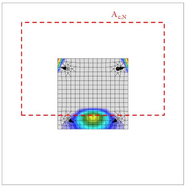
- \(N_{Rk,c}=N_{Rk,c}^0 \cdot \frac{A_{c,N}}{A_{c,N}^0} \cdot \psi_{s,N} \cdot \psi_{re,N} \cdot \psi_{ec,N} \cdot \psi_{M,N}\) – rezistența caracteristică a unui dispozitiv de fixare, a unui grup de dispozitive de fixare și a dispozitivelor de fixare întinse dintr-un grup în cazul smulgerii conului de beton
- \(N_{Rk,c}^0 = k_1 \sqrt{f_{ck}} h_{ef}^{1.5}\) – rezistența caracteristică a unui singur dispozitiv de fixare plasat în beton și neinfluențat de dispozitivele de fixare adiacente sau de marginile elementului de beton
- k1 – factor care ține seama de condiția betonului și tipul de ancoră; pentru ancorele cu cap turnate în cofraj (cu plăci tip șaibă) k1 = 8,9 pentru beton fisurat și k1 = 12,7 pentru beton nefisurat; pentru dispozitivele de fixare post-instalate (ancore drepte) k1 = 7,7 pentru beton fisurat și k1 = 11,0 pentru beton nefisurat
- fck – rezistența caracteristică la compresiune pe cilindru a betonului
- hef – adâncimea de încastrare a ancorului în beton; pentru trei sau mai multe margini apropiate, se aplică EN 1992-4, Cl. 7.2.1.4 (8) și se utilizează în formule \(h'_{ef} = \max \left \{ \frac{c_{max}}{c_{cr,N}} \cdot h_{ef}, \, \frac{s_{max}}{s_{cr,N}} \cdot h_{ef} \right \}\) efectiv în locul valorii inițiale pentru NRk,c0, ccr,N, scr,N, Ac,N, Ac,N0, ψs,N și ψec,N
- Ac,N – aria proiectată reală, limitată de suprapunerea conurilor de beton ale dispozitivelor de fixare adiacente, precum și de marginile elementului de beton
- Ac,N0 = scr,N2 – aria proiectată de referință, adică aria de beton a unei ancore individuale cu distanță mare între ancore și față de margine la suprafața betonului
- \(\psi_{s,N}=0.7+0.3 \cdot \frac{c}{c_{cr,N}} \le 1\) – factor care ține seama de perturbarea distribuției tensiunilor în beton datorită proximității unei margini a elementului de beton
- c – cea mai mică distanță față de margine
- ccr,N = 1,5 ∙ hef – distanța caracteristică față de margine pentru asigurarea transmiterii rezistenței caracteristice a unei ancore în cazul smulgerii conului de beton la încărcare de întindere
- \(\psi_{re,N}=0.5+\frac{h_{ef}}{200} \le 1\) – factor de exfoliere a stratului de acoperire
- \(\psi_{ec,N}=\frac{1}{1+2 \cdot (e_N / s_{cr,N})} \le 1\) – factor care ține seama de efectul de grup atunci când forțe de întindere diferite acționează asupra dispozitivelor de fixare individuale dintr-un grup; ψec,N se determină separat pentru fiecare direcție și se utilizează produsul ambilor factori
- eN – excentricitatea forței de întindere rezultante a dispozitivelor de fixare întinse față de centrul de greutate al dispozitivelor de fixare întinse
- scr,N = 2 ∙ ccr,N – distanța caracteristică dintre ancore pentru asigurarea rezistenței caracteristice a ancorelor în cazul smulgerii conului de beton la încărcare de întindere
- \(\psi_{M,N} = 2- \frac{z}{1.5 \cdot h_{ef}} \ge 1\) – factor care ține seama de efectul unei forțe de compresiune între dispozitivul de fixare și beton în cazul momentelor încovoietoare cu sau fără forță axială; acest parametru este egal cu 1 dacă c < 1,5 hef sau raportul dintre forța de compresiune (inclusiv compresiunea datorată încovoierii) și suma forțelor de întindere din ancore este mai mic de 0,8 sau z / hef ≥ 1,5
- z – brațul de pârghie interior al unui dispozitiv de fixare
- γMc = γc ∙ γinst – factor parțial de siguranță (EN 1992-4, Tabelul 4.1)
- γc – factor parțial de siguranță pentru beton (editabil în Configurarea codului)
- γinst – factor parțial de siguranță care ține seama de siguranța instalării unui sistem de ancoraj (editabil în Configurarea codului)
Aria conului de smulgere a betonului pentru un grup de ancore încărcate la întindere care formează un con comun de beton, Ac,N, este indicată prin linia roșie întreruptă.
Rezistența la smulgere (EN 1992-4, Cl. 7.2.1.5)
Rezistența la smulgere este verificată pentru ancorele turnate în cofraj cu plăci tip șaibă și dornuri cu cap conform EN 1992-4, Cl. 7.2.1.5:
\[ N_{Rd,p}=\frac{N_{Rk,p}}{\gamma_{Mc}} \]
unde:
- NRk,p = k2 ∙ Ah ∙ fck – rezistența caracteristică în cazul cedării prin smulgere
- k2 – coeficient dependent de condiția betonului, k2 = 7,5 pentru beton fisurat, k2 = 10,5 pentru beton nefisurat
- Ah – aria de reazem a capului ancorului; pentru placă tip șaibă circulară \(A_h = \frac{\pi}{4} \left ( d_h^2 - d^2 \right )\), pentru placă tip șaibă dreptunghiulară \(A_h = a_{wp}^2 - \frac{\pi}{4} d^2\)
- dh ≤ 6 th + d – diametrul capului dispozitivului de fixare
- th – grosimea capului dispozitivului de fixare cu cap
- d – diametrul tijei dispozitivului de fixare
- fck – rezistența caracteristică la compresiune pe cilindru a betonului
- γMc = γc ∙ γinst – factor parțial de siguranță (EN 1992-4, Tabelul 4.1)
- γc – factor parțial de siguranță pentru beton (editabil în Configurarea codului)
- γinst – factor parțial de siguranță care ține seama de siguranța instalării unui sistem de ancoraj (editabil în Configurarea codului)
Rezistența la smulgere (EN 1992-1-1, Cl. 8.4.4)
Rezistența la smulgere este verificată pentru ancorele turnate în cofraj cu cârlig conform EN 1992-1-1, Cl. 8.4.4. Se presupun bare netede care necesită o lungime de ancoraj dublă față de armătura nervurată (Tabelul 3.26 din BS 8110-1).
\[N_{Rd,p}=A_a \cdot f_{ya} \cdot \frac{l_b}{l_{bd}}\]
unde:
- Aa – aria secțiunii transversale efective a unei ancore
- fya – rezistența la curgere a ancorului
- lb – lungimea ancorului înglobată în beton
- \(l_{bd} = \alpha_1 \cdot \alpha_2 \cdot \alpha_3 \cdot \alpha_4 \cdot \alpha_5 \cdot l_{b,rqd}\) – lungimea de ancoraj de calcul
- \(\alpha_1\) – factor pentru efectul formei barelor presupunând acoperire adecvată
- \(\alpha_1 = 0.7\) pentru \(c_d > 3 \phi\)
- \(\alpha_1 = 1.0\) pentru \(c_d \le 3 \phi\)
- \(c_d = \min \{a/2, c_1\}\) – acoperire adecvată
- a – distanța liberă dintre ancore
- c1 – distanța liberă față de marginea blocului de beton
- \(\phi\) – diametrul ancorului
- \(\alpha_2 = 1.0 - 0.15 \frac{c_d - \phi}{\phi}\) – factor pentru efectul acoperirii minime cu beton; \(0.7 \le \alpha_2 \le 1.0\)
- \(\alpha_3 = 1.0\) – factor pentru efectul confinării prin armătură transversală
- \(\alpha_4 = 1.0 \) – factor pentru influența uneia sau mai multor bare transversale sudate de-a lungul lungimii de ancoraj de calcul
- \(\alpha_5=1.0\) – factor pentru efectul presiunii transversale față de planul de despicere de-a lungul lungimii de ancoraj de calcul
- \(l_{b,rqd} = \frac{\phi}{4} \frac{f_{ya}}{f_{bd}}\) – lungimea de ancoraj necesară
- \(f_{bd} = \frac{2.25 \cdot \eta_1 \cdot \eta_2 f_{ctd}}{2}\) – valoarea de calcul a tensiunii ultime de aderență (presupusă la jumătate față de armătura nervurată)
- \(\eta_1=1.0\) – coeficient legat de calitatea condiției de aderență și poziția barei în timpul betonării; se presupun condiții bune, ceea ce poate fi periculos în cazul rar al ancorelor orizontale plasate în partea superioară a betonului
- \(\eta_2=\min \{1.0, \frac{132-\phi}{100}\) – coeficient legat de diametrul barei
- \(f_{ctd}=\frac{\alpha_{ct} \cdot f_{ctk,0.05}}{\gamma_c}\) – valoarea de calcul a rezistenței la întindere a betonului
- \(\alpha_{ct}=1.0\) – coeficient care ține seama de efectele pe termen lung asupra rezistenței la întindere și de efectele nefavorabile
- \(f_{ctk,0.05}\) – rezistența caracteristică axială la întindere a betonului (cuantila 5%)
- \(\gamma_c\) – factor de siguranță pentru beton, editabil în Setările proiectului
Se adaugă mai multe reguli de alcătuire constructivă:
- Rezistența la curgere a ancorului nu trebuie să depășească 300 MPa (EN 1993-1-8 – 6.2.6.12 (5))
- Lungimea minimă de ancoraj \(l_{b,min}\) trebuie respectată (EN 1992-1-1 – Ecuația (8.6)):
\[ l_b \ge l_{b,min} = \max \{ 0.3 \cdot l_{b,rqd}, 10\cdot \phi , 100 \}\]
- Lungimea de ancoraj trebuie să fie suficientă pentru ca modul de cedare prin rupere la întindere a oțelului să fie determinant, în vederea facilitării proiectării plastice
Rezistența la smulgere (EN 1992-1-1, Cl. 8.4.4)
Rezistența la smulgere este verificată pentru armătură conform EN 1992-1-1, Cl. 8.4.4.
\[N_{Rd,p}=A_a \cdot f_{ya} \cdot \frac{l_b}{l_{bd}}\]
unde:
- Aa – aria secțiunii transversale efective a unei ancore
- fya – rezistența la curgere a ancorului
- lb – lungimea ancorului înglobată în beton
- \(l_{bd} = \alpha_1 \cdot \alpha_2 \cdot \alpha_3 \cdot \alpha_4 \cdot \alpha_5 \cdot l_{b,rqd}\) – lungimea de ancoraj de calcul
- \(\alpha_1\) – factor pentru efectul formei barelor presupunând acoperire adecvată
- \(\alpha_1 = 0.7\) pentru \(c_d > 3 \phi\)
- \(\alpha_1 = 1.0\) pentru \(c_d \le 3 \phi\)
- \(c_d = \min \{a/2, c_1\}\) – acoperire adecvată
- a – distanța liberă dintre ancore
- c1 – distanța liberă față de marginea blocului de beton
- \(\phi\) – diametrul ancorului
- \(\alpha_2 = 1.0 - 0.15 \frac{c_d - \phi}{\phi}\) – factor pentru efectul acoperirii minime cu beton; \(0.7 \le \alpha_2 \le 1.0\)
- \(\alpha_3 = 1.0\) – factor pentru efectul confinării prin armătură transversală
- \(\alpha_4 = 1.0 \) – factor pentru influența uneia sau mai multor bare transversale sudate de-a lungul lungimii de ancoraj de calcul
- \(\alpha_5=1.0\) – factor pentru efectul presiunii transversale față de planul de despicere de-a lungul lungimii de ancoraj de calcul
- \(l_{b,rqd} = \frac{\phi}{4} \frac{f_{ya}}{f_{bd}}\) – lungimea de ancoraj necesară
- \(f_{bd} = 2.25 \cdot \eta_1 \cdot \eta_2 f_{ctd}\) – valoarea de calcul a tensiunii ultime de aderență
- \(\eta_1=1.0\) – coeficient legat de calitatea condiției de aderență și poziția barei în timpul betonării; se presupun condiții bune, ceea ce poate fi periculos în cazul rar al ancorelor orizontale plasate în partea superioară a betonului
- \(\eta_2=\min \{1.0, \frac{132-\phi}{100}\) – coeficient legat de diametrul barei
- \(f_{ctd}=\frac{\alpha_{ct} \cdot f_{ctk,0.05}}{\gamma_c}\) – valoarea de calcul a rezistenței la întindere a betonului
- \(\alpha_{ct}=1.0\) – coeficient care ține seama de efectele pe termen lung asupra rezistenței la întindere și de efectele nefavorabile
- \(f_{ctk,0.05}\) – rezistența caracteristică axială la întindere a betonului (cuantila 5%)
- \(\gamma_c\) – factor de siguranță pentru beton, editabil în Setările proiectului
Se adaugă mai multe reguli de alcătuire constructivă:
- Lungimea minimă de ancoraj \(l_{b,min}\) trebuie respectată (EN 1992-1-1 – Ecuația (8.6)):
\[ l_b \ge l_{b,min} = \max \{ 0.3 \cdot l_{b,rqd}, 10\cdot \phi , 100 \}\]
- Lungimea de ancoraj trebuie să fie suficientă pentru ca modul de cedare prin rupere la întindere a oțelului să fie determinant, în vederea facilitării proiectării plastice
Rezistența la smulgere a altor tipuri de ancore nu este verificată și trebuie garantată de producător.
Rezistența la smulgere laterală a betonului (EN 1992-4, Cl. 7.2.1.8)
Cedarea prin smulgere laterală este verificată pentru ancorele turnate în cofraj cu placă tip șaibă și dornuri cu cap cu distanța față de margine c ≤ 0,5 hef conform EN 1992-4, Cl. 7.2.1.8. Ancorele sunt tratate ca grup dacă distanța dintre ele în apropierea marginii este s ≤ 4 c1. Ancorele cu coadă de rândunică pot fi verificate în același mod, dar valoarea Ah este necunoscută în software. Cedarea prin smulgere laterală a ancorelor cu coadă de rândunică poate fi determinată prin selectarea unei plăci tip șaibă cu dimensiunea corespunzătoare.
\[N_{Rd,cb} = \frac{N_{Rk,cb}}{\gamma_{Mc}}\]
unde:
- \(N_{Rk,cb} = N_{Rk,cb}^0 \cdot \frac{A_{c,Nb}}{A_{c,Nb}^0} \cdot \psi_{s,Nb} \cdot \psi_{g,Nb} \cdot \psi_{ec,Nb}\) – rezistența caracteristică în cazul cedării prin smulgere laterală a betonului
- \(N_{Rk,cb}^0 = k_5 \cdot c_1 \cdot \sqrt{A_h} \cdot \sqrt{f_{ck}}\) – rezistența caracteristică a unui singur dispozitiv de fixare, neinfluențat de dispozitivele de fixare adiacente sau de alte margini
- Ac,Nb – aria proiectată reală, limitată de suprapunerea corpurilor de smulgere laterală ale dispozitivelor de fixare adiacente, precum și de proximitatea marginilor elementului de beton sau de grosimea elementului
- Ac,Nb0 = (4 c1)2 – aria proiectată de referință a unui singur dispozitiv de fixare cu distanța față de margine egală cu c1
- \(\psi_{s,Nb} = 0.7+0.3 \frac{c_2}{2 c_1} \le 1\) – factor care ține seama de perturbarea distribuției tensiunilor în beton datorită proximității unui colț al elementului de beton
- \( \psi_{g,Nb} = \sqrt{n} + (1-\sqrt{n}) \frac{s_2}{4c_1} \ge 1 \) – factor care ține seama de efectul de grup
- \(\psi_{ec,Nb} = \frac{1}{1+2 e_N / s_{cr,Nb}} \le 1\) – factor care ține seama de efectul de grup, atunci când forțe diferite acționează asupra dispozitivelor de fixare individuale dintr-un grup
- k5 – parametru legat de starea betonului; pentru beton fisurat k5 = 8,7, pentru beton nefisurat k5 = 12,2
- c1 – distanța față de margine a dispozitivului de fixare în direcția 1 către cea mai apropiată margine
- c2 – distanța față de margine a dispozitivului de fixare perpendicular pe direcția 1, care reprezintă cea mai mică distanță față de margine într-un element îngust cu mai multe distanțe față de margine
- Ah – aria capului portant al dispozitivului de fixare; pentru placă tip șaibă circulară \(A_h = \frac{\pi}{4} \left ( d_h^2 - d^2 \right )\), pentru placă tip șaibă dreptunghiulară \(A_h = a_{wp}^2 - \frac{\pi}{4} d^2\)
- d – diametrul nominal al ancorului
- dh – diametrul plăcii tip șaibă circulare
- awp – dimensiunea laturii plăcii tip șaibă pătrate
- fck – rezistența caracteristică la compresiune pe cilindru a betonului
- n – numărul de dispozitive de fixare dintr-un rând paralel cu marginea elementului de beton
- s2 – distanța dintre dispozitivele de fixare dintr-un grup perpendicular pe direcția 1
- scr,Nb = 4 c1 – distanța necesară pentru ca un dispozitiv de fixare să dezvolte rezistența sa caracteristică la întindere împotriva cedării prin smulgere laterală
Rezistența la forfecare a oțelului ancorului (EN 1993-1-8 – Cl. 6.2.2)
Rezistența la forfecare a oțelului ancorului pentru ancorele turnate în cofraj cu placă tip șaibă și ancorele cu cârlig este determinată conform EN 1993-1-8 – 6.2.2 (7), indiferent de tipul de rezemare directă sau prin rost de mortar. Adăugarea frecării este problematică în practică și nu este luată în considerare. Baza pentru calculul conform Eurocod este modelul Laboratorului Stevin prezentat în această lucrare. Găurile trebuie să fie standard, nu supradimensionate, iar rezistența și grosimea mortarului trebuie să fie conform Cl. 6.2.5 (7).
\[F_{vb,Rd} = \min \{F_{1vb,Rd}, F_{2vb,Rd} \} \]
unde:
- \(F_{1vb,Rd} = \frac{\alpha_v \cdot f_{ub} \cdot A}{\gamma_{M2}}\) – rezistența la forfecare a ancorului din Tabelul 3.4
- αv = 0,6 pentru clasele 4.6, 5.6, 8.8 și 0,5 pentru clasele 4.8, 5.8, 6.8, 10.9
- fub – rezistența ultimă la întindere a bulonului
- A – aria secțiunii transversale efective a bulonului
- A = A pentru planul de forfecare în afara filetului; A este aria brută a secțiunii transversale a ancorului
- A = As pentru planul de forfecare interceptat de filet; As este aria secțiunii transversale efective a bulonului
- γM2 – factor de siguranță (EN 1993-1-8 – Tabelul 2.1; editabil în Setările proiectului)
- \(F_{2vb,Rd} = \frac{\alpha_b \cdot f_{ub} \cdot A_s}{\gamma_{M2}}\) – rezistența la forfecare a ancorului din Ecuația (6.2)
- \(\alpha_b = 0.44 - 0.0003 f_{yb}\) – coeficient dependent de rezistența la curgere a bulonului de ancoraj
- fyb – rezistența la curgere a ancorului; 235 MPa \(\le f_{yb} \le\) 640 MPa
- fub – rezistența ultimă la întindere a ancorului
- As – aria secțiunii transversale efective
De remarcat că \(F_{2vb,Rd}\) este întotdeauna determinant și că rezistența la forfecare rezultată în cazul rezemării: rost de mortar este în mod tipic semnificativ mai mare decât rezistența determinată conform EN 1992-4 – Cl. 7.2.2.3. Aceasta deoarece EN 1993-1-8 permite deformații mari și efecte de ordinul doi (forțe de întindere în ancore).
Rezistența la forfecare a oțelului ancorului (EN 1992-4 – Cl. 7.2.2.3)
Rezistența la forfecare a oțelului ancorului pentru dispozitivele de fixare post-instalate și dornurile cu cap turnate în cofraj este verificată conform EN 1992-4 – Cl. 7.2.2.3. Frecarea nu este luată în considerare. Forfecarea cu și fără braț de pârghie este recunoscută în funcție de setările operației de fabricare a plăcii de bază.
\[V_{Rd,s} = \frac{V_{Rk,s}}{\gamma_{Ms}}\]
Pentru rezemare: directă, se presupune forfecarea fără braț de pârghie (EN 1992-4 – Cl. 7.2.2.3.1):
VRk,s = k6 ∙ As ∙ fuk – rezistența caracteristică a unui singur dispozitiv de fixare în cazul cedării oțelului; pentru dispozitivele de fixare cu raportul hef / dnom < 5 și o clasă de rezistență la compresiune a betonului < C20/25, rezistența caracteristică VRk,s trebuie înmulțită cu un factor de 0,8.
Pentru rezemare: rost de mortar, se presupune forfecarea cu braț de pârghie (EN 1992-4 – Cl. 7.2.2.3.2):
\[V_{Rk,s}= \frac{\alpha_M \cdot M_{Rk,s}}{l_a}\]
unde:
- k6 = 0,6 pentru ancore cu fuk ≤ 500 MPa; k6 = 0,5 în celelalte cazuri
- As – aria de forfecare a ancorului; dacă este selectat planul de forfecare în filet, se utilizează aria redusă de filet; în caz contrar, se utilizează aria completă a tijei
- fuk – rezistența ultimă a bulonului de ancoraj
- αM = 2 – se presupune încastrare completă (EN 1992-4 – Cl. 6.2.2.3)
- \( M_{Rk,s} = M_{Rk,s}^0 \left ( 1 - \frac{N_{Ed}}{N_{Rd,s}} \right ) \) – rezistența caracteristică la încovoiere a ancorului redusă de forța de întindere din ancoră
- MRk,s0 = 1,2 Wel fub – rezistența caracteristică la încovoiere a ancorului (ETAG 001, Anexa C – Ecuația (5.5b))
- \( W_{el} = \frac{\pi d^3}{32}\) – modulul de rezistență al secțiunii ancorului
- d – diametrul bulonului de ancoraj; dacă este selectat planul de forfecare în filet, se utilizează diametrul redus de filet; în caz contrar, se utilizează diametrul nominal, dnom
- NEd – forța de întindere din ancoră
- NRd,s – rezistența la întindere a ancorului
- la = 0,5 dnom + tmortar + 0,5 tbp – brațul de pârghie
- tmortar – grosimea mortarului (grout)
- tbp – grosimea plăcii de bază
- γMs = 1,0 ∙ fuk / fyk ≥ 1,25 pentru fuk ≤ 800 MPa și fyk / fuk ≤ 0,8; γMs = 1,5 în celelalte cazuri – factor parțial de siguranță pentru cedarea oțelului (EN 1992-4 – Tabelul 4.1)
Rezistența la forfecare a oțelului ancorului (EN 1992-1-1 – Cl. 3.3.6)
Armătura sudată de placa de bază se află în afara domeniului de aplicare al EN 1992-4, iar regulile din EN 1992-1-1 se aplică. Acest cod nu furnizează nicio formulă specifică, ci mai degrabă o diagramă efort-deformație și aria secțiunii transversale care trebuie utilizate în calculele de proiectare conform Cl. 3.3.6. Datorită utilizării sudurii, care introduce incertitudini suplimentare, se utilizează un factor parțial de siguranță mai conservativ, \(\gamma_{M2}\).
\[F_{t,Rd} = \frac{A_s \cdot f_{ud}}{\sqrt{3}} \]
unde:
- \(A_s\) – aria secțiunii transversale efective
- \(f_{ud}=\frac{k \cdot f_{yk}}{\gamma_{M2}}\) – rezistența de calcul la întindere a armăturii
- \(k\) – factor de ductilitate
- \(f_{yk}\) – rezistența caracteristică la curgere a armăturii
- \(\gamma_{M2}\) – factor parțial de siguranță pentru buloane, suduri sau rupere prin întindere, editabil în Setările proiectului
Cedarea betonului prin efect de pârghie (EN 1992-4 – Cl. 7.2.2.4):
\[ V_{Rd,cp}= \frac{V_{Rk,cp}}{\gamma_{Mc}} \]
unde:
- VRk,cp = k8 ∙ NRk,c – rezistența caracteristică la cedarea betonului prin efect de pârghie
- k8 = 1 pentru hef < 60 mm; k8 = 2 pentru hef ≥ 60 mm (ETAG 001, Anexa C – Cl. 5.2.3.3)
- NRk,c – rezistența caracteristică a unui dispozitiv de fixare, a unui grup de dispozitive de fixare și a dispozitivelor de fixare întinse dintr-un grup în cazul smulgerii conului de beton; se presupune că toate ancorele sunt la întindere
- γMc = γc – factor parțial de siguranță (EN 1992-4 – Tabelul 4.1, γinst = 1,0 pentru încărcare la forfecare)
- γc – factor parțial de siguranță pentru beton (editabil în Configurarea codului)
Cedarea betonului la margine (EN 1992-4 – Cl. 7.2.2.5):
Cedarea betonului la margine este o cedare fragilă, iar cel mai defavorabil caz este verificat, adică numai ancorele situate în apropierea marginii transferă întreaga forță de forfecare care acționează pe întreaga placă de bază. Dacă ancorele sunt poziționate în model dreptunghiular, rândul de ancore de la marginea investigată transferă forța de forfecare. Dacă ancorele sunt poziționate neregulat, cele două ancore cele mai apropiate de marginea investigată transferă forța de forfecare. Sunt investigate două margini în direcția forței de forfecare, iar cazul cel mai defavorabil este prezentat în rezultate.
Notă: Dacă ancorele din apropierea marginii au găuri ovale, acestea nu sunt ignorate, ci sunt utilizate pentru această verificare conform codului ca și cum ar avea găuri standard (EN 1992-4 nu include găurile ovale în domeniul său de aplicare).

Marginile investigate în funcție de direcția rezultantei forței de forfecare
\[ V_{Rd,c} = \frac{V_{Rk,c}}{\gamma_{Mc}} \]
unde:
- \( V_{Rk,c}= V_{Rk,c}^0 \cdot \frac{A_{c,V}}{A_{c,V}^0} \cdot \psi_{s,V} \cdot \psi_{h,V} \cdot \psi_{ec,V} \cdot \psi_{\alpha,V} \cdot \psi_{re,V} \) – rezistența caracteristică a unui dispozitiv de fixare sau a unui grup de dispozitive de fixare încărcate spre margine
- \( V_{Rk,c}^0 = k_9 \cdot d_{nom}^\alpha \cdot l_f^\beta \cdot f_{ck}^{0.5} \cdot c_1^{1.5}\) – valoarea inițială a rezistenței caracteristice a unui dispozitiv de fixare încărcat perpendicular pe margine
- k9 – factor care ține seama de condiția betonului; k9 = 1,7 pentru beton fisurat, k9 = 2,4 pentru beton nefisurat
- \( \alpha = 0.1 \left ( \frac{l_f}{c_1} \right ) ^{0.5} \)
- \( \beta = 0.1 \left ( \frac{d_{nom}}{c_1} \right ) ^{0.2} \)
- lf = min (hef, 12 dnom) pentru dnom ≤ 24 mm; lf = min [hef, max (8 dnom, 300 mm)] pentru dnom > 24 mm – lungimea efectivă a ancorului la forfecare
- hef – adâncimea de încastrare a ancorului în beton
- c1 – distanța de la ancoră la marginea investigată; pentru dispozitive de fixare într-un element îngust și subțire, se utilizează în schimb distanța efectivă \( c'_1=\max \left \{ \frac{c_{2,max}}{1.5}, \, \frac{h}{1.5}, \, \frac{s_{2,max}}{3} \right \} \)
- c2 – distanța mai mică față de marginea betonului perpendiculară pe distanța c1
- dnom – diametrul nominal al ancorului
- Ac,V0 = 4,5 c12 – aria conului de beton al unei ancore individuale la suprafața laterală a betonului neafectată de margini (aria proiectată de referință a unui dispozitiv de fixare sau a unui grup de dispozitive de fixare)
- Ac,V – aria reală a conului de beton al ancorării la suprafața laterală a betonului (aria corpului idealizat de smulgere a betonului al unui dispozitiv de fixare sau al unui grup de dispozitive de fixare, limitată de suprapunerea conurilor de beton ale dispozitivelor de fixare adiacente, de marginile paralele cu direcția de încărcare presupusă și de grosimea elementului)
- \(\psi_{s,V} = 0.7+0.3 \frac{c_2}{1.5 c_1} \le 1.0 \) – factor care ține seama de perturbarea distribuției tensiunilor în beton datorită altor margini ale elementului de beton asupra rezistenței la forfecare
- \( \psi_{h,V} = \left ( \frac{1.5 c_1}{h} \right ) ^ {0.5} \ge 1.0 \) – factor care ține seama de faptul că rezistența la forfecare nu scade proporțional cu grosimea elementului, așa cum se presupune prin raportul Ac,V / Ac,V0
- \( \psi_{ec,V} = \frac{1}{1+2 e_V / (3c_1)} \le 1 \) – factor care ține seama de efectul de grup atunci când forțe de forfecare diferite acționează asupra ancorelor individuale dintr-un grup
- \( \psi_{\alpha,V} = \sqrt{\frac{1}{(\cos \alpha_V)^2 + (0.5 \sin \alpha_V)^2}} \ge 1 \) – ține seama de unghiul αV dintre forța aplicată, V, și direcția perpendiculară pe marginea liberă a elementului de beton
- ψre,V = 1,0 – factor care ține seama de efectul tipului de armătură utilizat în betonul fisurat
- h – înălțimea blocului de beton
- γMc = γc – factor parțial de siguranță (EN 1992-4 – Tabelul 4.1, γinst = 1,0 pentru încărcare la forfecare)
- γc – factor parțial de siguranță pentru beton (editabil în Configurarea codului)
Interacțiunea întindere-forfecare în oțel (EN 1993-1-8 – Tabelul 3.4)
Interacțiunea întindere-forfecare pentru ancorele turnate în cofraj cu placă tip șaibă sau cârlig nu este necesară deoarece este inclusă implicit în verificarea la forfecare a ancorului.
Explicație la Steel support din Olanda:
Pentru verificarea buloanelor obișnuite, Tabelul 3.4 din EN 1993-1-8 include o formulă pentru interacțiunea forței normale și a forței de forfecare. Cu toate acestea, această formulă se aplică numai buloanelor dintr-o îmbinare obișnuită (oțel-oțel) și nu ancorelor dintr-o îmbinare cu placă de bază a stâlpului. La verificarea rezistenței la forfecare a ancorului, a fost deja luată în considerare o forță de întindere în bulon egală cu rezistența la curgere; a se vedea Ec. 6.2 din Cl. 6.2.2 (7) din EN 1993-1-8. Tensiunea de întindere reală care apare în ancoră nu este, prin urmare, relevantă. Această metodă de calcul se bazează pe teste efectuate la TU Delft. Aceste reguli de calcul din Eurocod sunt identice cu regulile de calcul din seria TGB. Explicația regulii de calcul este inclusă în NEN 6772, dar nu și în EN 1993-1-8. Pentru îmbinările cu placă de bază a stâlpului, este, prin urmare, suficient să se efectueze numai verificările separate pentru întindere și forfecare.
Interacțiunea întindere-forfecare în oțel (EN 1992-4 – Tabelul 7.3)
Interacțiunea întindere-forfecare pentru dispozitivele de fixare post-instalate, dornurile cu cap turnate în cofraj și armătura este determinată separat pentru modurile de cedare ale oțelului și betonului conform Tabelului 7.3. Interacțiunea în oțel este verificată conform Ecuației (7.54). Interacțiunea în oțel este verificată pentru fiecare ancoră separat.
\[ \left ( \frac{N_{Ed}}{N_{Rd,s}} \right )^2 + \left ( \frac{V_{Ed}}{V_{Rd,s}} \right )^2 \le 1.0 \]
Interacțiunea întindere-forfecare în beton
Interacțiunea în beton este verificată conform Ecuației (7.55).
\[ \left ( \frac{N_{Ed}}{N_{Rd,i}} \right )^{1.5} + \left ( \frac{V_{Ed}}{V_{Rd,i}} \right )^{1.5} \le 1.0 \]
Se va lua cea mai mare valoare a \(N_{Ed} / N_{Rd,i} \) și \(V_{Ed} / V_{Rd,i} \) pentru diferitele moduri de cedare. De remarcat că valorile \(N_{Ed}\) și \(N_{Rd,i}\) aparțin adesea unui grup de ancore.
Ancore cu rezemare: Spațiu liber
O ancoră cu tipul de rezemare Spațiu liber este proiectată ca un element bară încărcat de forță de forfecare, moment încovoietor și forță de compresiune sau întindere. Aceste eforturi interioare sunt determinate de modelul cu elemente finite. Ancora este fixată pe ambele părți, o parte se află la 0,5×d sub nivelul betonului, iar cealaltă parte se află în mijlocul grosimii plăcii. Lungimea de flambaj este presupusă conservativ ca dublul lungimii elementului bară. Se utilizează modulul de rezistență plastic. Elementul bară este proiectat conform EN 1993-1-1. Forța de forfecare poate reduce rezistența la curgere a oțelului conform Cl. 6.2.8, dar lungimea minimă a ancorului pentru a permite montarea piuliței sub placa de bază asigură că ancora cedează la încovoiere înainte ca forța de forfecare să atingă jumătate din rezistența la forfecare. Reducerea nu este, prin urmare, necesară. Interacțiunea momentului încovoietor cu rezistența la compresiune sau întindere este evaluată conform Cl. 6.2.1.
Rezistența la forfecare (EN 1993-1-1 Cl. 6.2.6):
\[ V_{pl,Rd} = \frac{A_V f_y / \sqrt{3}}{\gamma_{M2}} \]
unde:
- AV = 0,844 As – aria de forfecare
- As – aria bulonului redusă de filet
- fy – rezistența la curgere a bulonului
- γM2 – factor parțial de siguranță
Rezistența la întindere (EN 1993-1-8 – Cl. 3.6.1):
\[ F_{t,Rd}=\frac{c k_2 f_{ub} A_s}{\gamma_{M2}} \ge F_t \]
unde:
- c – reducerea rezistenței la întindere a buloanelor cu filet tăiat conform EN 1993-1-8 – Cl. 3.6.1. (3), editabil în Configurarea codului
- k2 = 0,9 – factor din Tabelul 3.4 din EN 1993-1-8
- fub – rezistența ultimă a bulonului de ancoraj
- As – aria secțiunii transversale efective a bulonului de ancoraj
- γM2 – factor de siguranță (EN 1993-1-8 – Tabelul 2.1; editabil în Configurarea codului)
Rezistența la compresiune (EN 1993-1-1 Cl. 6.3):
\[ F_{c,Rd} = \frac{\chi A_s f_y}{\gamma_{M2}} \]
unde:
- \( \chi = \frac{1}{\Phi + \sqrt{\Phi^2 - \bar\lambda^2}} \le 1 \) – factor de reducere la flambaj
- \( \Phi = 0.5 \left [1+ \alpha (\bar\lambda - 0.2) + \bar\lambda^2 \right ] \) – valoare pentru determinarea factorului de reducere la flambaj χ
- α = 0,49 – factor de imperfecțiune pentru curba de flambaj c (corespunzătoare secțiunii circulare pline)
- \( \bar\lambda = \sqrt{\frac{A_s f_y}{N_{cr}}} \) – zveltețea relativă
- \( N_{cr} = \frac{\pi^2 E I}{L_{cr}^2} \) – forța critică Euler
- \( I = \frac{\pi d_s^4}{64} \) – momentul de inerție al bulonului
- Lcr = 2 l – lungimea de flambaj; se presupune în mod conservativ că bulonul este încastrat în beton și poate roti liber la placa de bază
- l – lungimea elementului bulon egală cu jumătate din grosimea plăcii de bază + spațiul liber + jumătate din diametrul bulonului; se presupune în mod conservativ că șaiba și piulița nu sunt strânse pe suprafața betonului (ETAG 001 – Anexa C – Cl. 4.2.2.4)
Rezistența la încovoiere (EN 1993-1-1 Cl. 6.2.5):
\[ M_{pl,Rd} = \frac{W_{pl} f_y}{\gamma_{M2}} \]
- \( W_{pl}= \frac{d_s^3}{6} \) – modulul de rezistență al secțiunii bulonului
- fy – rezistența la curgere a bulonului
- γM2 – factor parțial de siguranță
Gradul de utilizare al oțelului ancorului (EN 1993-1-1 Cl. 6.2.1)
\[ \frac{N_{Ed}}{N_{Rd}} + \frac{M_{Ed}}{M_{Rd}} \le 1 \]
unde:
- NEd – forța de calcul la întindere (pozitivă) sau la compresiune (semn negativ)
- NRd – rezistența de calcul la întindere (pozitivă, Ft,Rd) sau la compresiune (semn negativ, Fc,Rd)
- MEd – momentul încovoietor de calcul
- MRd = Mpl,Rd – rezistența de calcul la încovoiere
Alcătuire constructivă
Verificarea alcătuirii constructive a ancorelor se efectuează dacă opțiunea este selectată în Configurarea codului. Se verifică numai distanța minimă dintre ancore (măsurată de la ax la ax). Distanța minimă diferă pentru fiecare tip de ancoră și este indicată în Specificația Tehnică Europeană a Produsului. Utilizatorii pot modifica valoarea limită a distanței în Configurarea codului ca multiplu al diametrului bulonului de ancoraj.
Distanțele față de marginea plăcilor de oțel urmează regulile pentru buloane, adică e = 1,2 este recomandat în Tabelul 3.3 din EN 1993-1-8. Utilizatorul poate modifica această valoare în Configurarea codului.
Testați astăzi cea mai recentă versiune a IDEA StatiCa
Verificarea conform codului a blocurilor de beton (EN)
Betonul de sub placa de bază este simulat prin subsolul Winkler cu rigiditate uniformă, care furnizează tensiunile de contact. Tensiunea medie pe aria efectivă determinată conform EN 1993-1-8 este utilizată pentru verificarea la compresiune.
Rezistența betonului la compresiune triaxială este determinată pe baza EN 1993-1-8 prin calculul rezistenței de calcul la presiune a betonului în rost, fjd, sub aria efectivă, Aeff, a plăcii de bază. Rezistența de calcul la presiune a rostului, fjd, este evaluată conform Cl. 6.2.5 din EN 1993-1-8 și Cl. 6.7 din EN 1992-1-1. Calitatea și grosimea mortarului de nivelare sunt introduse prin coeficientul de rost, βjd. Pentru o calitate a mortarului egală sau superioară calității blocului de beton, se presupune βjd = 1.0; EN 1993-1-8 recomandă valoarea βjd = 0.67. Aria efectivă, Aeff,cm, de sub placa de bază este estimată a avea forma secțiunii transversale a stâlpului mărită cu lățimea suplimentară de rezemare, c.
\[ c = t \sqrt{\frac{f_y}{3 f_{jd} \gamma_{M0}}} \]
unde t este grosimea plăcii de bază, fy este limita de curgere a plăcii de bază, iar γM0 este factorul parțial de siguranță pentru oțel.
Aria efectivă se calculează prin iterație până când diferența dintre lățimile suplimentare de rezemare ale iterației curente și ale celei anterioare |ci – ci–1 | este mai mică de 1 mm. Pentru prima iterație, aria plăcii de bază este considerată ca arie de rezemare, Ac0.
Aria în care betonul este comprimat este preluată din rezultatele analizei cu Metoda Elementelor Finite. Această arie în compresiune, Aeff,FEM, permite determinarea poziției axei neutre. Utilizatorul poate modifica această arie editând „Arie efectivă – influența dimensiunii plasei" în Configurarea codului. Valoarea implicită este 0.1, pentru care au fost efectuate studiile de verificare. Nu se recomandă scăderea acestei valori. Creșterea acestei valori face evaluarea rezistenței la presiune a betonului mai conservatoare. Valoarea din Configurarea codului determină limita ariei, Aeff,FEM; de exemplu, valoarea 0.1 ia în considerare doar zonele în care tensiunea în beton este mai mare de 0.1 ori tensiunea maximă în beton, σc,max. Intersecția ariei în compresiune, Aeff,FEM, și a ariei efective, Aeff,cm, permite evaluarea rezistenței pentru o bază de stâlp încărcată în general, de orice formă a stâlpului, cu orice elemente de rigidizare, și este notată Aeff. Tensiunea medie σ pe aria efectivă, Aeff, este determinată ca forța de compresiune împărțită la aria efectivă. Verificarea componentei se face în tensiuni σ ≤ fjd.
Rezistența betonului la compresiune concentrată:
\[ f_{jd}= \beta_j k_j \frac{f_{ck}}{\gamma_c} \]
Factorul de concentrare care ține seama de creșterea rezistenței la compresiune a betonului datorită stării triaxiale de tensiuni:
\[ k_j=\sqrt{\frac{A_{c1}}{A_{eff}}} \le 3.0 \]
unde Ac1 este aria de rezemare determinată conform EN 1992-1-1 – Cl. 6.7. Aria trebuie să fie concentrică și geometric similară cu aria de rezemare Aeff.
Tensiunea medie sub placa de bază:
\[ \sigma = \frac{N}{A_{eff}} \]
Gradul de utilizare la compresiune [%]:
\[ Ut = \frac{\sigma}{f_{jd}} \]
unde:
- fck – rezistența caracteristică la compresiune a betonului
- βj = 0.67 – factor de calitate a mortarului de nivelare, editabil în Configurarea codului
- γc – factor de siguranță pentru beton
- Aeff – aria efectivă pe care se distribuie forța normală N a stâlpului
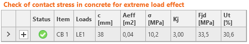
Aria efectivă, Aeff,cm, calculată conform EC pentru compresiune pură, este marcată cu linie întreruptă. Reprezentarea grafică arată modul de verificare. Aria efectivă calculată, Aeff,fem, este marcată cu verde. Aria efectivă finală, Aeff, pentru verificarea tensiunilor de contact este evidențiată prin hașurare.
În cazuri rare, în special pentru baze de stâlp încărcate numai cu forță de întindere (compresiunea în beton este cauzată de efectul de pârghie) sau cu forță de întindere și moment încovoietor, intersecția ariilor Aeff,cm și Aeff,fem este extrem de mică sau inexistentă. În astfel de cazuri, forțele de compresiune sunt în general foarte mici, verificarea este în afara domeniului de aplicare al Eurocodului, iar betonul comprimat nu este verificat.
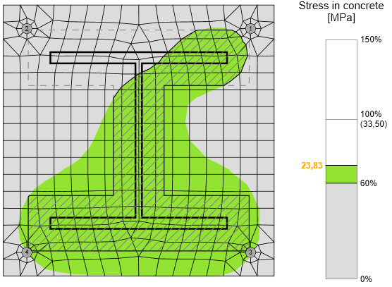
Sensibilitatea la dimensiunea plasei
Această procedură de evaluare a rezistenței betonului la compresiune este independentă de plasa plăcii de bază, după cum se poate observa în figurile de mai jos. Este ilustrată pe exemplul evaluării betonului la compresiune conform EC. Au fost investigate două cazuri: încărcare prin compresiune pură de 1200 kN și încărcare printr-o combinație de forță de compresiune de 1200 kN și moment încovoietor de 90 kN.
Influența numărului de elemente asupra predicției rezistenței betonului la compresiune în cazul compresiunii pure
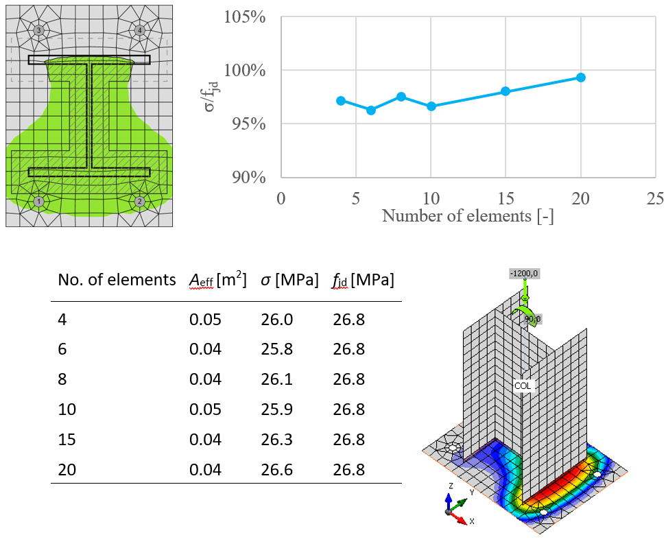
Influența numărului de elemente asupra predicției rezistenței betonului la compresiune în cazul compresiunii și încovoierii
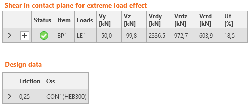
Forfecare în blocul de beton
Forfecarea în blocul de beton poate fi preluată prin unul dintre cele trei mijloace:
- Frecare
\( Ut = \frac{V}{V_{Rd}} \)
Vrd = N Cf - Pivot de forfecare
\( Ut = \max \left ( \frac{V_y}{V_{Rd,y}}, \, \frac{V_z}{V_{Rd,z}}, \, \frac{V}{V_{c,Rd}} \right ) \) \(V_{Rd,y} = \frac{A_{Vy} f_y}{\sqrt{3} \gamma_{M0}} \)
\( V_{Rd,z} = \frac{A_{Vz} f_y}{\sqrt{3} \gamma_{M0}} \)
\( V_{c,Rd} = A \sigma_{Rd,max} \)
Pivotul de forfecare și sudurile sunt de asemenea verificate prin MEF. - Ancore
Verificarea se efectuează conform ETAG 001 – Anexa C
unde:
- AV,y, AV,z – ariile de forfecare ale secțiunii transversale a pivotului de forfecare în direcția axelor y și z
- fy – limita de curgere
- γM0 – factor de siguranță
- Vy – componenta forței tăietoare în planul plăcii de bază în direcția y
- Vz – componenta forței tăietoare în planul plăcii de bază în direcția z
- V – forța tăietoare (suma vectorială a ambelor componente ale forței tăietoare)
- N – forța perpendiculară pe placa de bază
- Cf – coeficientul de frecare dintre oțel și beton/mortar de nivelare; editabil în Configurarea codului
- A = l b – aria proiectată a pivotului de forfecare, excluzând porțiunea de deasupra suprafeței betonului
- l – lungimea pivotului de forfecare, excluzând porțiunea de deasupra suprafeței betonului
- b – lățimea proiectată a pivotului de forfecare în direcția încărcării de forfecare
- σRd,max = k1 v' fcd – tensiunea maximă care poate fi aplicată la marginile nodului
- k1 = 1 – factor (EN 1992-1-1 – Ecuația (6.60))
- v' = 1 – fck / 250 – factor (EN 1992-1-1 – Ecuația (6.57N))
- \( f_{cd} = \alpha_{cc} \frac{f_{ck}} {\gamma_c} \) – rezistența de calcul la compresiune a betonului
- αcc – coeficient pentru efectele de lungă durată asupra rezistenței la compresiune a betonului
- fck – rezistența caracteristică la compresiune a betonului
- γc – factor de siguranță pentru beton
Proiectare la capacitate (EN)
Proiectarea la capacitate este o parte a verificării seismice și asigură că îmbinarea are o capacitate de deformație suficientă.
Obiectivul proiectării la capacitate este de a confirma că o clădire prezintă un comportament ductil controlat pentru a evita prăbușirea în cazul unui cutremur de nivel de proiectare. Se preconizează că articulația plastică apare în elementul disipativ, iar toate elementele non-disipative ale îmbinării trebuie să fie capabile să transfere în siguranță forțele datorate curgerii în elementul disipativ. Elementul disipativ este de obicei un element de tip grindă într-un cadru cu noduri rigide, dar poate fi și, de exemplu, o placă de capăt. Factorul de siguranță nu se aplică elementelor disipative. Două coeficienți sunt atribuiți elementului disipativ:
- γov – factor de suprarezistență – EN 1998-1, Cl. 6.2; valoarea recomandată este γov = 1,25; editabil în materiale
- γsh – factor de ecruisare; valorile recomandate sunt γsh = 1,2 pentru grinda din cadrul cu noduri rigide, γsh = 1,0 în celelalte cazuri; editabil în operație
Diagrama materialului este modificată conform figurii următoare:
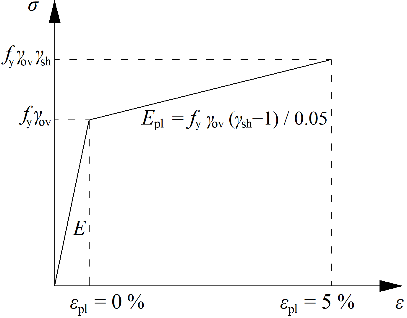
Rezistența sporită a elementului disipativ permite introducerea încărcărilor care determină apariția articulației plastice în elementul disipativ. În cazul cadrului cu noduri rigide și al grinzii ca element disipativ, grinda trebuie încărcată cu My,Ed = γovγshfyWpl,y și forța tăietoare corespunzătoare Vz,Ed = –2 My,Ed / Lh, unde:
- fy – rezistența caracteristică la curgere
- Wpl,y – modulul de rezistență plastic al secțiunii
- Lh – distanța dintre articulațiile plastice de pe grindă
În cazul unei îmbinări asimetrice, grinda trebuie încărcată atât cu momente încovoietoare pozitive, cât și negative, și cu forțele tăietoare corespunzătoare.
Plăcile elementelor disipative sunt excluse din verificare.
Analiza la flambaj (EN)
Rezistența la încărcare a elementelor zvelte poate fi determinată printr-o combinație de analiză liniară la flambaj și analiză materială neliniară.
Există cinci categorii de analiză structurală prin Metoda Elementelor Finite, cu următoarele ipoteze:
- Material liniar, geometric liniar
- Material neliniar, geometric liniar
- Material liniar, pierdere liniară a stabilității – flambaj
- Material liniar, geometric neliniar cu imperfecțiuni
- Material neliniar, geometric neliniar cu imperfecțiuni
O procedură de calcul care combină abordările 2 și 3 – neliniaritate materială și analiză de stabilitate – este menționată în Capitolul 8 al EN 1993-1-6. Verificarea rezistenței la flambaj pe baza rezultatelor obținute prin MEF este descrisă în Anexa B a EN 1993-1-5. Această procedură este utilizată pentru o gamă largă de structuri, cu excepția cojilor foarte zvelte, unde analiza geometric neliniară cu imperfecțiuni inițiale este mai adecvată (4 și 5).
Procedura utilizează amplificatori de încărcare α, care sunt obținuți ca rezultate ale analizei MEF și permit estimarea rezistenței post-flambaj a îmbinărilor.
Coeficientul de încărcare, αult,k, este determinat prin atingerea capacității plastice fără a lua în considerare neliniaritatea geometrică. Verificarea capacității plastice și determinarea automată generală a αult,k sunt implementate în software-ul dezvoltat.
Factorul critic de flambaj, αcr, este determinat prin analiza MEF a stabilității liniare. Acesta este determinat automat în software folosind același model MEF ca pentru calculul αult,k. Trebuie menționat că punctul critic din punct de vedere al rezistenței plastice nu este neapărat evaluat în primul mod critic de flambaj. Mai multe moduri de flambaj trebuie evaluate într-o îmbinare complexă, deoarece acestea sunt legate de diferite părți ale îmbinării.
Zveltețea adimensională a plăcii, \( \bar \lambda_p \), pentru modul de flambaj analizat, se determină:
\[ \bar \lambda_p = \sqrt{\frac{\alpha_{ult,k}}{\alpha_{cr}}} \]
Factorul de reducere la flambaj ρ se determină conform Anexei B a EN 1993-1-5. Factorul de reducere depinde de zveltețea plăcii. Curba de flambaj utilizată ilustrează influența factorului de reducere asupra zvelteței plăcii. Factorul de flambaj furnizat, aplicabil elementelor neuniforme, se bazează pe curbele de flambaj ale unei grinzi. Verificarea se bazează pe criteriul de curgere von Mises și pe metoda tensiunilor reduse. Rezistența la flambaj se evaluează astfel:
\[ \frac{\alpha_{ult,k} \rho}{\gamma_{M2}} \ge 1 \]
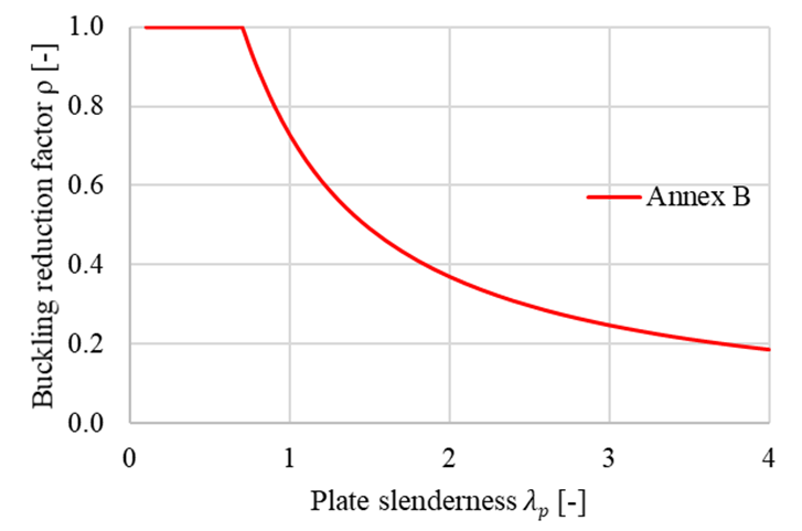
Factorul de reducere la flambaj ρ conform EN 1993-1-5 Anexa B
Deși procesul pare simplu, acesta este general, robust și ușor de automatizat. Avantajul procedurii constă în analiza MEF avansată a întregii îmbinări, care poate fi aplicată geometriilor generale. Mai mult, aceasta este inclusă în standardele Eurocode în vigoare. Analiza numerică avansată oferă o imagine de ansamblu rapidă asupra comportamentului global al structurii și al părților sale critice și permite rigidizarea rapidă pentru prevenirea instabilităților.
Zveltețea limită, λp, este furnizată în Anexa B a EN 1993-1-5 și stabilește toate cazurile care trebuie evaluate conform procedurii anterioare. Rezistența este limitată de flambaj pentru zveltețe a plăcii mai mare de 0,7. Odată cu scăderea zvelteței, rezistența este guvernată de deformația plastică. Factorul critic de flambaj limită pentru zveltețea plăcii egală cu 0,7, iar rezistența la flambaj egală cu rezistența plastică, poate fi obținută astfel:
\[ \alpha_{cr} = \frac{\alpha_{ult,k}}{\bar \lambda_p^2} = \frac{1}{0.7^2} = 2.04 \]
Influența zvelteței plăcii asupra rezistenței plastice, Mult,k, și a rezistenței la flambaj, MCBFEM, este prezentată în figura de mai jos. Diagrama prezintă rezultatele unui studiu numeric al unui element de rigidizare triunghiular într-o îmbinare de cadru portal.
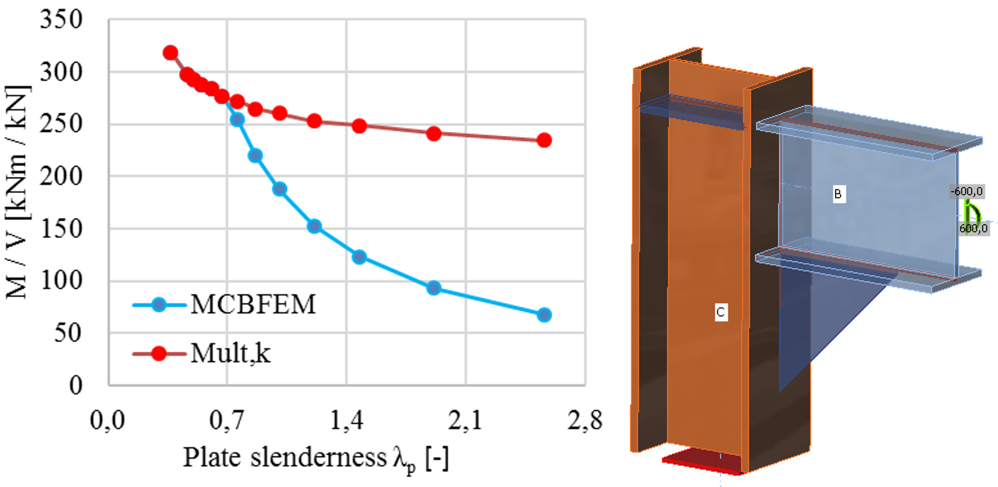
Influența zvelteței plăcii asupra rezistenței îmbinării de cadru portal cu element de rigidizare zvelт
Clasificarea rosturilor (EN)
Rosturile sunt clasificate în funcție de rigiditatea rostului în:
- Rigide – rosturi cu modificare nesemnificativă a unghiurilor inițiale dintre elemente,
- Semi-rigide – rosturi care se presupune că au capacitatea de a furniza un grad cunoscut și fiabil de încastrare la încovoiere,
- Articulate – rosturi care nu dezvoltă momente încovoietoare.
Rosturile sunt clasificate conform EN 1993-1-8 – Cl. 5.2.2.
- Rigide – \( \frac{S_{j,ini} L_b}{E I_b} \ge k_b \)
- Semi-rigide – \( 0.5 < \frac{S_{j,ini} L_b}{E I_b} < k_b \)
- Articulate – \( \frac{S_{j,ini} L_b}{E I_b} \le 0.5 \)
unde:
- Sj,ini – rigiditatea inițială a rostului; rigiditatea rostului se consideră liniară până la 2/3 din Mj,Rd
- Lb – lungimea teoretică a elementului analizat; se setează în proprietățile elementului
- E – modulul de elasticitate Young
- Ib – momentul de inerție al elementului analizat
- kb = 8 pentru cadre în care sistemul de contravântuire reduce deplasarea orizontală cu cel puțin 80%; kb = 25 pentru alte cadre, cu condiția că în fiecare nivel Kb/Kc ≥ 0.1. Valoarea kb = 25 este utilizată dacă utilizatorul nu setează „sistem contravântuit" în Configurarea codului.
- Mj,Rd – rezistența de calcul la moment a rostului
- Kb = Ib / Lb
- Kc = Ic / Lc
Legătură orizontală
Îmbinările trebuie proiectate pentru a transmite forța de întindere generată de efectele de ordinul doi – un stâlp este eliminat și planșeul acționează ca o membrană.
Reazeme
Se analizează un singur element, iar toate celelalte elemente sunt încastrate la capete. Asupra elementului analizat trebuie aplicată doar forța normală, astfel că tipul de model este setat la N-Vy-Vz (momentele încovoietoare și torsiunea sunt restricționate).
Încărcare
Forța normală care acționează asupra elementului analizat trebuie determinată conform EN 1993-1-7, Cl. A.5.1:
Pentru legăturile interioare:
\[T_i=0.8(g_k+\psi q_k) s L \ge 75 \textrm{ kN} \]
Pentru legăturile perimetrale:
\[T_p=0.4(g_k+\psi q_k) s L \ge 75 \textrm{ kN} \]
unde:
- \(g_k\) – încărcarea permanentă caracteristică
- \(q_k\) – încărcarea variabilă caracteristică
- \(s\) – distanța dintre legături
- \(L\) – deschiderea legăturii
- \(\psi\) – factorul relevant din expresia pentru combinarea efectelor acțiunilor pentru situația de calcul accidentală (adică \(\psi_1\) sau \(\psi_2\) conform expresiei (6.11b) din EN 1990).
Modelul de material și verificări
Conform SCI P358: Joints in steel construction: Simple Joints to Eurocode 3 – Anexa A, se introduce factorul parțial de siguranță pentru legătura orizontală, \(\gamma_{Mu}\), cu valoarea implicită 1,1, editabilă în Configurarea codului. Acest factor de siguranță se utilizează pentru plăci, șuruburi și suduri în analiza legăturii orizontale.
Se anticipează încărcări și deformații extreme, iar proiectarea plăcilor se bazează pe rezistența ultimă a plăcilor, \(f_u\). De aceea, modelul de material pentru analiza cu elemente finite se comportă elastic până la \(f_u / \gamma_{Mu}\). Panta ramurii plastice este modulul de elasticitate Young \(E/1000\). Verificarea se efectuează pentru limita de deformație plastică de 5%.
Rezistențele șuruburilor și sudurilor se calculează cu \(\gamma_{Mu}\) în loc de \(\gamma_{M2}\). Utilizând valorile implicite ale factorilor parțiali de siguranță, rezistențele la încărcare sunt mai mari cu aproximativ 14% față de starea limită ultimă.
Se presupune că șuruburile pretensionate alunecă și sunt verificate ca șuruburi obișnuite, strânse manual.
Referințe
EN 1993-1-7: Eurocode 1 – Acțiuni asupra structurilor – Partea 1-7: Acțiuni generale – Acțiuni accidentale, CEN, 2006.
SCI P358: Joints in steel construction: Simple Joints to Eurocode 3