Improvements
- New tool for activating BIM links – directly from the starting application of IDEA StatiCa
- Position of loads in the connection – Node/ Bolts/ Position
- Default items for templates - material, bolt, cleat
NEW BIM links with FEA (CAE) programs
- Staad.PRO (Bentley)
- SCIA Engineer (SCIA Nemetschek)
- RSTAB (Dlubal)
- Revit (Autodesk)
AxisVM and RFEM – link now runs via a direct wizard
BIM links with CAD programs
- Link Tekla Structures – conversion table for recognizing of cross-sections and bolts
- Link Advance Steel - conversion table for recognizing of cross-sections and bolts
- Import cross-sections from Advance Steel
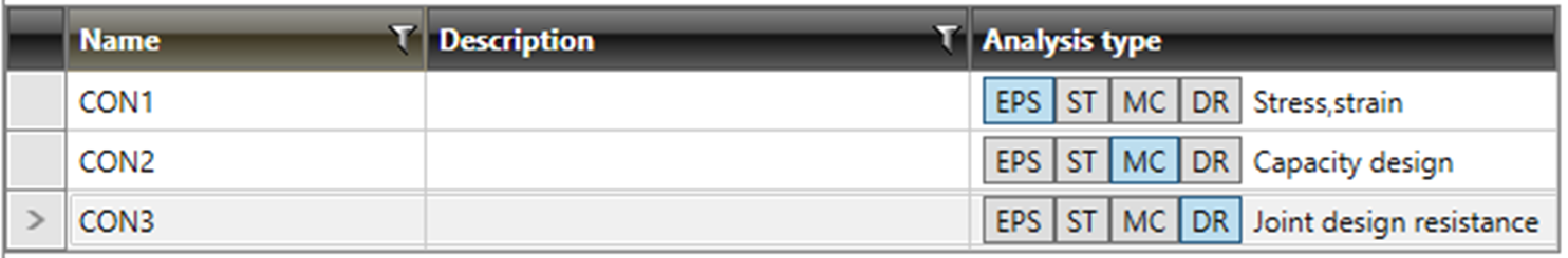
More options of joint analysis
IDEA Connection provides Stress/strain analysis of the whole joint and stiffness analysis of a connected member. Now we added Member Capacity Design and Design Joint Resistance. The first one is needed for design of structures in seismic regions, the second one helps to understand the safety and capacity of design of the whole joint.
Member Capacity Design
IDEA Connection checks the connection on applied design load. In many regions with the danger of seismicity is required to check the connection on the maximal moment which can be taken by connected member. IDEA Connection now checks the connection on applied design load. We calculate that moment in the software and apply it on the specific member. All other members in the joint are supported.

The value of moment is calculated and cannot be changed.

Moment is calculated differently for EN and AISC.
Capacity design EN 1998
Rd >= 1,1 * γov * Rfy
Rd – Resistance of non-dissipative connection
γo - 1,25
Rfy – Yield strength
Capacity design AISC 341-10
Mpe = 1,1 * Ry * Fy * Zx
Mpe - The expected moment at the plastic hinge
Fy – Yield strength
Ry - Ratio of the expected yield stress to the specified minimum yield (table A3.1)
Zx - is the plastic section modulus
Connections designed on maximal moment usually need to be much more stiffed than connections in regular structures.
It is important to mention that the connected member is not checked and this is not the scope of this functionality. It has to be properly designed in the global analysis of the structure.
This feature is available only in Enhanced (the highest) version of IDEA Connection.
Design Joint Resistance
Structural engineers usually design steel connections/joints so that they are able to carry the known design load. But it is also useful to know how far the design is from the limit state, or else, how big is the reserve in the design and how safe it is. This can be done very easily with the new type of analysis of version 8 – Design joint resistance.
The user inputs the design load like in standard design. The software automatically increases proportionally all load components until one of the checks is not satisfied. The user gets the ratio of maximal load to the design load. Also, a simple diagram is provided.

This feature is available only in Enhanced (the highest) version of IDEA Connection.
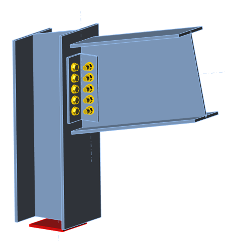
Manufacturing operations
The wide set of manufacturing operations helps to model the steel joint of any topology. Designer can now work with steel rods (circular profile). Existing fin and cleat connections were improved and equipped with more functionality.
Steel rod
Until now designers could not use rods with circular profile in their model. This option is implemented in 8.0 and the user can find this cross-section in the profile library.
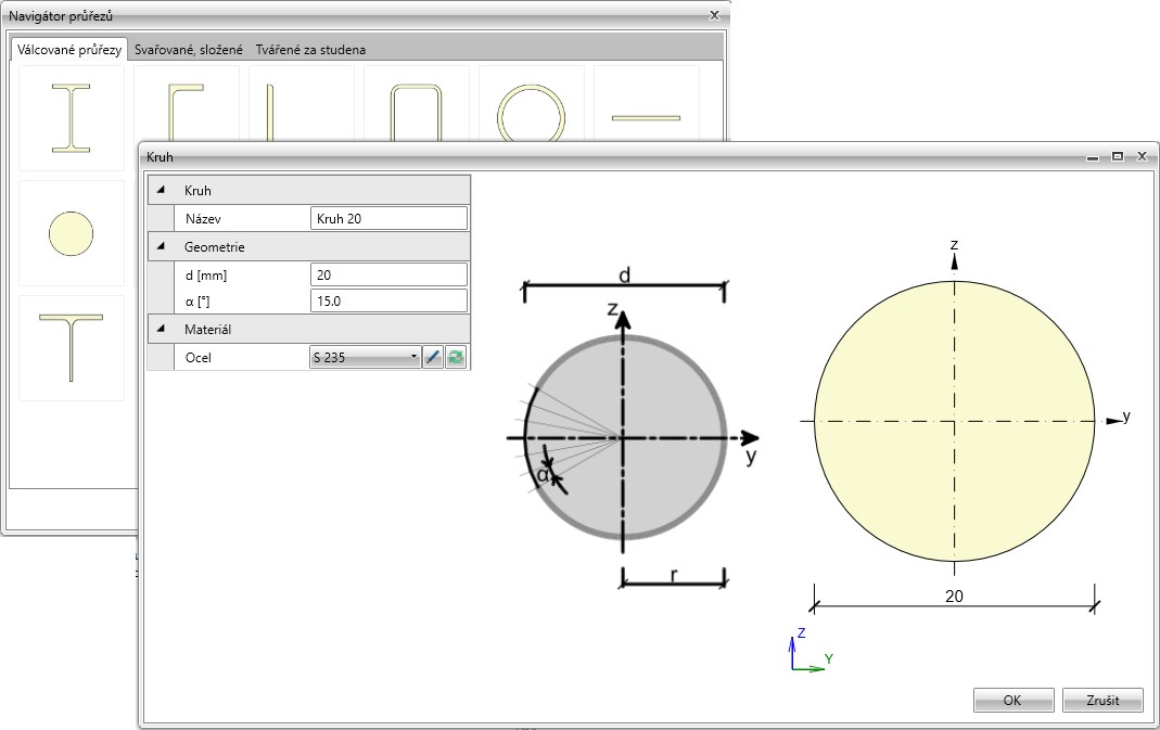
Circular profile can be used with connecting and gusset plates. In this case, the profile is not converted into steel plates like all others, and we also do not present results on them – it has to be done in the global design of the member. The weld is checked as all others in the joint.

Cleat
Cleat connection now can be applied also on pitched members.
The same functionality as we have for end plates was also implemented here. Two members that are connected on opposite sides can be now resolved in only one operation.
Fin plate
Fin plate is a typical shear connection of the vertical web of the profile. We enlarged this functionality to be able to connect any plate of a member. This allows the user to model for instance typical seismic connections. The end-cut of a member is now a part of the operation.

Formulas in result tables
IDEA StatiCa Connection already provided all necessary code check results in table format, where the user can see all the input values and the final results of checks, like for example checks for bolts and welds. But it is also very good to know for transparency reasons what is behind those numbers, meaning which formula is used, and which article of code has been applied. This was a frequently asked feature from our users and we are happy to say that is is now available.
The results tables look like in version 7.

When the user clicks on the + button in the relevant line, this line is “expanded” and all background formulas and values are shown.

Position of loads in the connection
The position of the load effect has a big influence in the correct design of the connection. As this was a source of misunderstandings, especially for new users, we implemented in the new version a choice to automatically define the position of the load between 3 different options: In node/ In bolts/ In position.


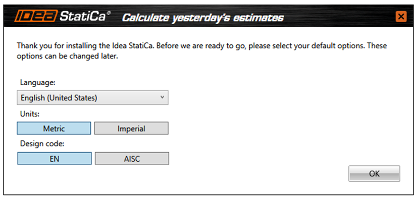
Improvements in code/unit customization
National environment is now set when the program is started for the first time.
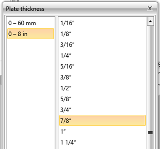
Proper sets of thicknesses plates and welds for the US market are now available.
Plate thickness:
Welds:

User can simply click on “arrow” button to set the next item from the product line.
Bolts:

New tools are available also for metric units.
Links with FEA programs
StaadPRO

RSTAB

CAD Links
- Link Tekla – conversion table for recognizing of cross-sections and bolts
- Link Advance Steel - conversion table for recognizing of cross-sections and bolts
- Import cross-sections from Advance Steel
Installation of BIM links
