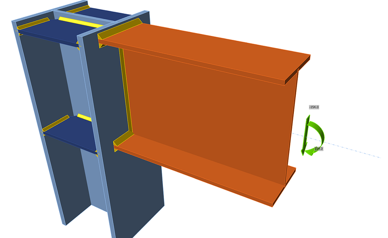
Welded portal frame eaves moment connection
Description
In this chapter, the component-based finite element method (CBFEM) for a welded portal frame eaves moment connection is verified on the component method (CM). An open section beam is welded to an open section column. The column is stiffened with two horizontal stiffeners opposite to beam flanges. Compressed plates, e.g. horizontal stiffeners of a column, column web panel in shear, compressed beam flange, are limited to 3rd class to avoid buckling. The rafter is loaded by shear force and bending moment.
Analytical model
Five components are examined in the study, namely the web panel in shear, the column web in transverse compression, the column web in transverse tension, the column flange in bending, and the beam flange in compression. All components are designed according to EN 1993-1-8:2005. Fillet welds are designed not to be the weakest component in the joint. The verification study of a fillet weld in a stiffened beam-to-column joint is in chapter 4.4.
Web panel in shear
The thickness of the column web is limited by slenderness to avoid stability problem; see EN 1993‑1‑8:2005, Cl 6.2.6.1(1). A class 4 column web panel in shear is studied in chapter 6.2. Two contributions to the load capacity are considered: resistance of the column panel in shear and the contribution from the frame mechanism of the column flanges and horizontal stiffeners; see EN 1993‑1‑8:2005, Cl. 6.2.6.1 (6.7 and 6.8).
Column web in transverse compression
Effect of the interaction of the shear load is considered; see EN 1993-1-8:2005, Cl. 6.2.6.2, Tab. 6.3. Influence of longitudinal stress in the column panel is considered; see EN 1993-1-8:2005, Cl. 6.2.6.2(2). The horizontal stiffeners are included in the load capacity of this component.
Column web in transverse tension
Effect of the interaction of the shear load is considered; see EN 1993-1-8:2005, Cl. 6.2.6.2, Tab. 6.3. The horizontal stiffeners are included in the load capacity of this component.
Column flange in bending
Horizontal stiffeners brace column flange; this component is not considered.
Beam flange in compression
The horizontal beam is designed to be class 3 cross-section or better to avoid buckling.
Overview of the considered examples and the material are given in the Tab. 9.1.1. Geometry of the joint with dimensions is shown in Fig. 9.1.1. The considered parameters in the study are beam cross-section, column cross-section, and thickness of the column web panel.
Tab. 9.1.1 Examples overview
| Example | Material | Beam | Column | Column stiffener | |||||
| fy | fu | E | \(\gamma_{M0}\) | \(\gamma_{M2}\) | Section | Section | bs | ts | |
| [MPa] | [MPa] | [GPa] | [-] | [-] | [mm] | [mm] | |||
| IPE140 | 235 | 360 | 210 | 1 | 1,25 | IPE140 | HEB260 | 73 | 10 |
| IPE160 | 235 | 360 | 210 | 1 | 1,25 | IPE160 | HEB260 | 82 | 10 |
| IPE180 | 235 | 360 | 210 | 1 | 1,25 | IPE180 | HEB260 | 91 | 10 |
| IPE200 | 235 | 360 | 210 | 1 | 1,25 | IPE200 | HEB260 | 100 | 10 |
| IPE220 | 235 | 360 | 210 | 1 | 1,25 | IPE220 | HEB260 | 110 | 10 |
| IPE240 | 235 | 360 | 210 | 1 | 1,25 | IPE240 | HEB260 | 120 | 10 |
| IPE270 | 235 | 360 | 210 | 1 | 1,25 | IPE270 | HEB260 | 135 | 10 |
| IPE300 | 235 | 360 | 210 | 1 | 1,25 | IPE300 | HEB260 | 150 | 10 |
| IPE330 | 235 | 360 | 210 | 1 | 1,25 | IPE330 | HEB260 | 160 | 10 |
| IPE360 | 235 | 360 | 210 | 1 | 1,25 | IPE360 | HEB260 | 170 | 10 |
| IPE400 | 235 | 360 | 210 | 1 | 1,25 | IPE400 | HEB260 | 180 | 10 |
| IPE450 | 235 | 360 | 210 | 1 | 1,25 | IPE450 | HEB260 | 190 | 10 |
| IPE500 | 235 | 360 | 210 | 1 | 1,25 | IPE500 | HEB260 | 200 | 10 |
| Example | Material | Beam | Column | Column stiffener | |||||
| fy | fu | E | \(\gamma_{M0}\) | \(\gamma_{M2}\) | Section | Section | bs | ts | |
| [MPa] | [MPa] | [GPa] | [-] | [-] | [mm] | [mm] | |||
| HEB160 | 235 | 360 | 210 | 1 | 1,25 | IPE330 | HEB160 | 160 | 10 |
| HEB180 | 235 | 360 | 210 | 1 | 1,25 | IPE330 | HEB180 | 160 | 10 |
| HEB200 | 235 | 360 | 210 | 1 | 1,25 | IPE330 | HEB200 | 160 | 10 |
| HEB220 | 235 | 360 | 210 | 1 | 1,25 | IPE330 | HEB220 | 160 | 10 |
| HEB240 | 235 | 360 | 210 | 1 | 1,25 | IPE330 | HEB240 | 160 | 10 |
| HEB260 | 235 | 360 | 210 | 1 | 1,25 | IPE330 | HEB260 | 160 | 10 |
| HEB280 | 235 | 360 | 210 | 1 | 1,25 | IPE330 | HEB280 | 160 | 10 |
| HEB300 | 235 | 360 | 210 | 1 | 1,25 | IPE330 | HEB300 | 160 | 10 |
| HEB320 | 235 | 360 | 210 | 1 | 1,25 | IPE330 | HEB320 | 160 | 10 |
| HEB340 | 235 | 360 | 210 | 1 | 1,25 | IPE330 | HEB340 | 160 | 10 |
| HEB360 | 235 | 360 | 210 | 1 | 1,25 | IPE330 | HEB360 | 160 | 10 |
| HEB400 | 235 | 360 | 210 | 1 | 1,25 | IPE330 | HEB400 | 160 | 10 |
| HEB450 | 235 | 360 | 210 | 1 | 1,25 | IPE330 | HEB450 | 160 | 10 |
| HEB500 | 235 | 360 | 210 | 1 | 1,25 | IPE330 | HEB500 | 160 | 10 |
| Example | Material | Beam | Column | Column stiffener | ||||||
| fy | fu | E | \(\gamma_{M0}\) | \(\gamma_{M2}\) | Section | Section | tw | bs | ts | |
| [MPa] | [MPa] | [GPa] | [-] | [-] | [mm] | [mm] | [mm] | |||
| tw4 | 235 | 360 | 210 | 1 | 1,25 | IPE330 | HEA320 | 4 | 160 | 10 |
| tw5 | 235 | 360 | 210 | 1 | 1,25 | IPE330 | HEA320 | 5 | 160 | 10 |
| tw6 | 235 | 360 | 210 | 1 | 1,25 | IPE330 | HEA320 | 6 | 160 | 10 |
| tw7 | 235 | 360 | 210 | 1 | 1,25 | IPE330 | HEA320 | 7 | 160 | 10 |
| tw8 | 235 | 360 | 210 | 1 | 1,25 | IPE330 | HEA320 | 8 | 160 | 10 |
| tw9 | 235 | 360 | 210 | 1 | 1,25 | IPE330 | HEA320 | 9 | 160 | 10 |
| tw10 | 235 | 360 | 210 | 1 | 1,25 | IPE330 | HEA320 | 10 | 160 | 10 |
| tw11 | 235 | 360 | 210 | 1 | 1,25 | IPE330 | HEA320 | 11 | 160 | 10 |
| tw12 | 235 | 360 | 210 | 1 | 1,25 | IPE330 | HEA320 | 12 | 160 | 10 |
| tw13 | 235 | 360 | 210 | 1 | 1,25 | IPE330 | HEA320 | 13 | 160 | 10 |
| tw14 | 235 | 360 | 210 | 1 | 1,25 | IPE330 | HEA320 | 14 | 160 | 10 |
| tw15 | 235 | 360 | 210 | 1 | 1,25 | IPE330 | HEA320 | 15 | 160 | 10 |
| tw16 | 235 | 360 | 210 | 1 | 1,25 | IPE330 | HEA320 | 16 | 160 | 10 |

Fig. 9.1.1 Joint geometry and dimensions
Numerical model
Nonlinear elastic-plastic material status is investigated in each layer of an integration point. Assessment is based on the maximum strain given according to EN 1993-1-5:2006 by the value of 5%.
Global behavior
Comparison of the global behavior of a portal frame moment connection, described by moment-rotation diagram, is presented. Main characteristics of the moment-rotation diagram are initial stiffness, elastic resistance, and design resistance. An open section beam IPE 330 is welded to a column HEB 260 in the example. A portal frame moment connection with horizontal stiffeners in the column is considered according to component method as a rigid joint with Sj,ini = ∞. Therefore a joint without horizontal stiffeners in the column is analyzed. The moment-rotation diagram is shown in Fig. 9.1.2, and the results are summarised in Tab. 9.1.2. The results show very good agreement in initial stiffness and joint global behavior.
Tab. 9.1.2 Rotational stiffness of a portal frame moment connection in CBFEM and CM
| CM | CBFEM | CM/CBFEM | ||
| Initial stiffness Sj,ini | [kNm/rad] | 48423,7 | 58400,0 | 0,83 |
| Elastic resistance 2/3 Mj,Rd | [kNm] | 93,3 | 93,0 | 1,00 |
| Design resistance Mj,Rd | [kNm] | 140,0 | 139,0 | 0,99 |

Fig. 9.1.2 Moment-rotation diagram for a joint without column stiffeners
Verification of resistance
The results calculated by CBFEM are compared with CM. The comparison is focused on the design resistance and the critical component. The study is performed for three different parameters: beam cross-section, column cross-section, and thickness of the column web panel.
An open section column HEB 260 is used in an example where the parameter is beam cross-section. The column is stiffened with two horizontal column stiffeners of thickness 10 mm opposite to the beam flanges. The width of stiffeners is corresponding to the width of beam flange. The beam IPE sections are selected from IPE 140 to IPE 500. The results are shown in Tab. 9.1.3. The influence of beam cross-section on the design resistance of a welded portal frame moment connection is shown in Fig. 9.1.3.
Tab. 9.1.3 Design resistances and critical components in CBFEM and CM
| Parameter | Component method | CBFEM | ||
| Resistance | Critical component | Resistance | Critical component | |
| [kN/kNm] | [kN/kNm] | |||
| IPE140 | 24 | Beam flange in compression | 27 | Beam flange in compression |
| IPE160 | 33 | Beam flange in compression | 34 | Beam flange in compression |
| IPE180 | 44 | Beam flange in compression | 48 | Beam flange in compression |
| IPE200 | 59 | Beam flange in compression | 67 | Beam flange in compression |
| IPE220 | 77 | Beam flange in compression | 80 | Beam flange in compression |
| IPE240 | 98 | Beam flange in compression | 103 | Beam flange in compression |
| IPE270 | 113 | Beam flange in compression | 125 | Beam flange in compression |
| IPE300 | 142 | Web panel in shear | 142 | Beam flange in compression |
| IPE330 | 155 | Web panel in shear | 145 | Web panel in shear |
| IPE360 | 168 | Web panel in shear | 167 | Web panel in shear |
| IPE400 | 186 | Web panel in shear | 183 | Web panel in shear |
| IPE450 | 209 | Web panel in shear | 202 | Web panel in shear |
| IPE500 | 231 | Web panel in shear | 223 | Web panel in shear |

Fig. 9.1.3 Sensitivity study of beam size in a portal frame moment connection
An open section beam IPE330 is used in an example where the parameter is column cross-section. The column is stiffened with two horizontal column stiffeners with a thickness of 10 mm opposite to the beam flanges. The width of stiffeners is corresponding to the width of beam flange. The combined width of stiffeners is 160 mm. The column sections are selected from HEB 160 to HEB 500. The results are shown in Tab. 9.1.4. The influence of column cross-section on the design resistance of a welded portal frame moment connection is shown in Fig. 9.1.4.
Tab. 9.1.4 Design resistances and critical components of a moment connection in CBFEM and CM
| Parameter | Component method | CBFEM | ||
| Resistance | Critical component | Resistance | Critical component | |
| [kN/kNm] | [kN/kNm] | |||
| HEB160 | 73 | Web panel in shear | 70 | Web panel in shear |
| HEB180 | 84 | Web panel in shear | 88 | Web panel in shear |
| HEB200 | 103 | Web panel in shear | 101 | Web panel in shear |
| HEB220 | 116 | Web panel in shear | 124 | Web panel in shear |
| HEB240 | 139 | Web panel in shear | 139 | Web panel in shear |
| HEB260 | 155 | Web panel in shear | 145 | Web panel in shear |
| HEB280 | 170 | Web panel in shear | 179 | Beam flange in compression |
| HEB300 | 198 | Web panel in shear | 196 | Beam flange in compression |
| HEB320 | 216 | Web panel in shear | 226 | Beam flange in compression |
| HEB340 | 226 | Beam flange in compression | 240 | Beam flange in compression |
| HEB360 | 228 | Beam flange in compression | 245 | Beam flange in compression |
| HEB400 | 234 | Beam flange in compression | 251 | Beam flange in compression |
| HEB450 | 241 | Beam flange in compression | 258 | Beam flange in compression |
| HEB500 | 248 | Beam flange in compression | 266 | Beam flange in compression |

Fig. 9.1.4 Sensitivity study of column size in a portal frame moment connection
Third example presents a portal frame moment connection made out of an open section beam IPE 330 and column HEA 320. The parameter is the thickness of the column web. The column is stiffened with two horizontal column stiffeners with a thickness of 10 mm and width 160 mm. The column web thickness is chosen from 4 to 16 mm. The results are summarised in Tab. 9.1.5. The influence of column web thickness on the design resistance of a welded portal frame moment connection is shown in Fig. 9.1.5.
Tab. 9.1.5 Design resistances and critical components of a moment connection in CBFEM and CM
| Parameter | Component method | CBFEM | ||
| Resistance | Critical component | Resistance | Resistance | |
| [kN/kNm] | [kN/kNm] | [kN/kNm] | ||
| tw4 | 82 | Web panel in shear | 99 | Web panel in shear |
| tw5 | 94 | Web panel in shear | 115 | Web panel in shear |
| tw6 | 106 | Web panel in shear | 131 | Web panel in shear |
| tw7 | 118 | Web panel in shear | 147 | Web panel in shear |
| tw8 | 130 | Web panel in shear | 162 | Web panel in shear |
| tw9 | 142 | Web panel in shear | 177 | Web panel in shear |
| tw10 | 155 | Web panel in shear | 190 | Beam flange in compression |
| tw11 | 167 | Web panel in shear | 203 | Beam flange in compression |
| tw12 | 179 | Web panel in shear | 216 | Beam flange in compression |
| tw13 | 191 | Web panel in shear | 227 | Beam flange in compression |
| tw14 | 203 | Web panel in shear | 236 | Beam flange in compression |
| tw15 | 215 | Beam flange in compression | 240 | Beam flange in compression |
| tw16 | 222 | Beam flange in compression | 241 | Beam flange in compression |
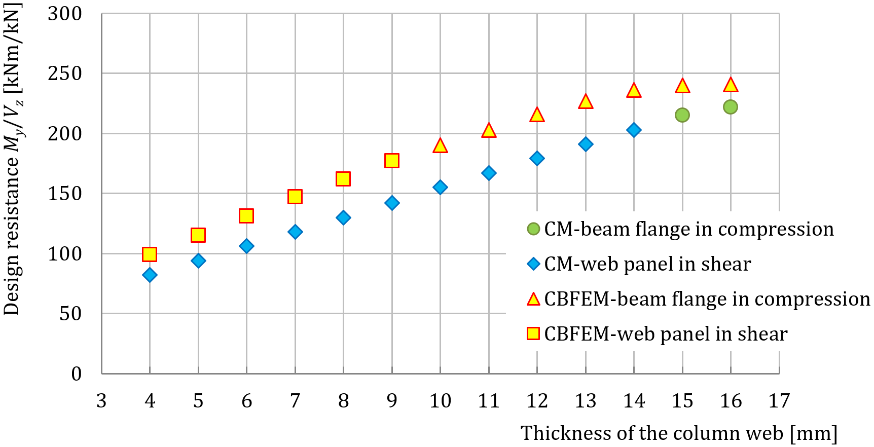
Fig. 9.1.5 A sensitivity study of column web thickness
To illustrate the accuracy of the CBFEM model, the results of the parametric studies are summarized in a diagram comparing the resistances of CBFEM and component method; see Fig. 9.1.6. The results show that the difference between the two calculation methods is less than 5%, which is a generally acceptable value. The study with parameter column web thickness gives higher resistance for CBFEM model compared to component method. This difference is caused by considering welded cross-sections. The transfer of shear load is in component method considered only in web and contribution of the flanges is neglected.

Fig. 9.1.6 Verification of CBFEM to CM
Benchmark example
Inputs
Column
- Steel S235
- HEB260
- Column offset over beam: 20 mm
Beam
- Steel S235
- IPE330
Column stiffeners
- Thickness ts = 10 mm
- Width 80 mm
- Opposite to beam flanges
Weld
- Beam flange: fillet weld throat thickness af = 9 mm
- Beam web: fillet weld throat thickness aw = 5 mm
- Butt weld around stiffeners
Outputs
- Design resistance in shear VRd = –145 kN
- Design resistance in bending MRd = 145 kNm
- Critical component: Column web panel in shear