1. The objective
The objective of this article is the verification of the GMNIA (geometrically and materially nonlinear analysis with imperfections) module of the IDEA Member application. The resulting resistances from IDEA Member are compared to EN 1993-1-1 [1] analytical solution for beams in bending.
2. Model description
A total of 18 individual cases was analyzed to verify the GMNIA module. All of them share the same cross-section IPE 240 and the same steel grade S 235. Three different loading conditions were investigated (A – end moments, B – force in the middle, C – continuous load). Six relative slenderness values were verified ranging from 0.6 to 1.6.
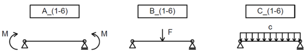
Fig. 1: Various load cases used for verification
3. Initial imperfections
Four approaches were used to calculate the initial imperfection of a beam in bending. These are designated A, B, C, and D. The A, B, and C approach uses the initial imperfection for the weak axis buckling multiplied by a factor of k = 0.5; as specified in EN 1993-1-1 Clause 5.3.4 (3) [1]. The initial imperfection according to approach D is determined directly for lateral torsional buckling.
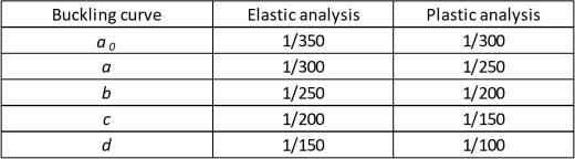
Approach A – according to EN 1993-1-1:2005, Table 5.1:
Tab. 1: Design value of initial bow imperfection e0/L for members
Approach B – according to prEN 1993-1-1:2020, second draft [2], Clause 5.3.3.1:
\[ \frac{e_0}{L}=\frac{α}{ε} \beta \]
where:
- e0 – initial imperfection
- α – imperfection factor depending on the relevant buckling curve according to 1993-1-1, Table 6.1 [1]
- \( \varepsilon = \sqrt{\frac{235}{f_y}} \)
- fy – column yield strength [MPa]
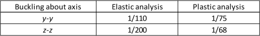
- β – reference relative bow imperfection according to Table 2
- L – member length
Tab. 2: Reference relative bow imperfection
Approach C – EUGLI (Equivalent Unique Global and Local Initial Imperfection) method according to EN 1993-1-1:2005, Clause 5.3.2 (11) [1]:
\[ e_0=\alpha (\bar \lambda - 0.2) \frac{M_{Rk}}{N_{Rk}} \]
where
- e0 – initial imperfection
- α – imperfection factor depending on the relevant buckling curve according to 1993-1-1, Table 6.1 [1]
- \( \bar \lambda \) – member relative slenderness
- NRk – characteristic resistance to normal force of a cross-section
- MRk – characteristic moment resistance of a cross-section
Approach D – according to [3]:
\[ e_0=\alpha_{LT} (\bar \lambda_{LT} - 0.2) \frac{M_{Rk}}{N_{Rk}} \]
where
- e0 – initial imperfection
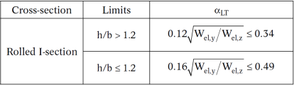
- αLT – imperfection factor from Table 3
- \( \bar \lambda_{LT} \) – member relative slenderness
- NRk – characteristic resistance to normal force of a cross-section
- MRk – characteristic moment resistance of a cross-section
Tab. 3: Imperfection factors for calculation of e0
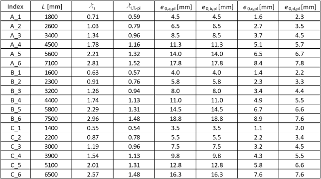
The resulting initial imperfection values are summarized in the table below. Note that for this cross-section and steel grade, approaches A and B give the same values.
Tab. 4: Resulting initial imperfection values
4. Analytical solution
The following approach according to EN 1993-1-1, Clauses 6.3.2.1 and 6.3.2.2 [1] is used to calculate the beam’s buckling resistance:
\[ \bar \lambda_{LT} = \sqrt{\frac{W_{pl,y} f_y}{M_{cr}}} \]
\[ \phi_{LT} = 0.5 \left [1 + \alpha_{LT} \left (\bar \lambda_{LT} - 0.2 \right ) + \bar \lambda_{LT} ^2 \right] \]
\[ \chi_{LT} = \frac{1}{\phi_{LT} + \sqrt{\phi_{LT}^2 - \bar \lambda_{LT} ^2}} \]
\[ M_{b,Rd} = \frac{\chi_{LT} W_{pl,y} f_y}{\gamma_{M1}} \]
5. Results
The ultimate resistances (for initial imperfections A = B, C and D) from IDEA Member are compared to analytical values for a rolled cross-section (EN) and for its representation without the web-flange radii (Ew) as well. Finally, results from the ANSYS software (A) [4] are presented, using the initial imperfections based on approach C.
Tab. 5: Resulting moment resistance values
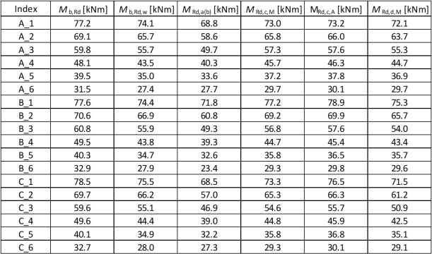
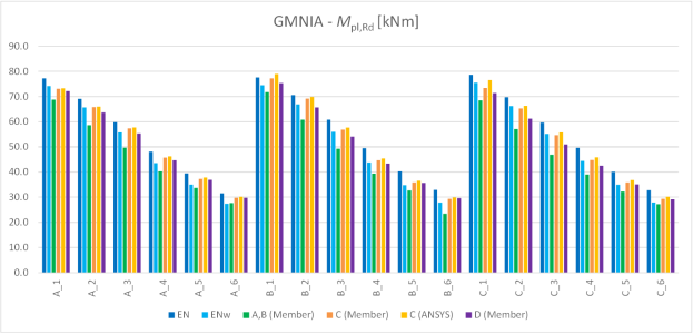
Chart 1: Resulting moment resistance values
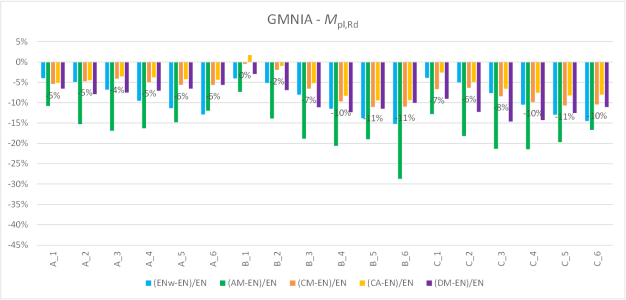
Chart 2: Comparison of resulting moment resistances
The results of GMNIA are conservative compared to the Eurocode solution. This is in part caused by the cross-section modeling in IDEA Member, this influence is between 5–10 % as can be seen from the blue column values in the chart above.
Comparing the two orange columns (Member and ANSYS), a good agreement with a numerical solution in ANSYS is evident.
The initial imperfection choice plays a major role in the resulting resistance. Using the initial imperfections A or B, the resulting moment resistances are 10–30 % lower compared to Eurocode. Methods C and D are only slightly conservative (< 10 %) compared to the Eurocode analytical solution for a real rolled cross-section. However, they are very close to the expected value calculated analytically for a cross-section without the web-flange radii.
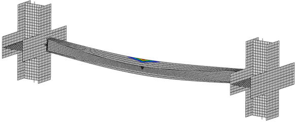
Fig. 2: Deformed shape at the ultimate resistance and plastic strain of the B_4 model
6. Literature and References
[1] EN 1993-1-1: Eurocode 3: Design of steel structures – Part 1-1: General rules and rules for buildings, CEN, 2005.
[2] prEN 1993-1-1: Eurocode 3: Design of steel structures – Part 1-1: General rules and rules for buildings, second draft, CEN, 2017.
[3] Snijder, H. H., van der Aa, R. P., Hofmeyer, H., & van Hove, B. W. E. M. (2018). Lateral torsional buckling design imperfections for use in non-linear FEA. Steel Construction: Design and Research, 11(1), 49-56.
[4] Aa, R.P. van der: Numerical assessment of the design imperfections for steel beam lateral torsional buckling, Master thesis, report 2015.96, Eindhoven University of Technology, Eindhoven, Dept. of the Built Environment, Structural Design, The Netherlands, 2015.