Geometric modification of cross-sections
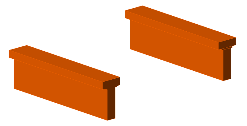
Reduction of the cross-section is automatically performed for structures defined as a beam or frame joint (defined by the x-axis and a cross-section). This modification is automatically applied on cross-sections with very wide flanges (Fig. 11) and is based on the assumption that a compression stress field would expand from the wall at a 45° angle, so the aforementioned reduced width would be the maximum width capable of transferring loads
Note that the method of determining the effective width flange implemented in CSFM is different from the one stated in 5.3.2.1 EN 1992-1-1 (2015) or in 9.2.4.4 ACI 318-19. Besides geometry, Eurocode-based effective width flange is explicitly affected by the span lengths and boundary conditions of a structure.
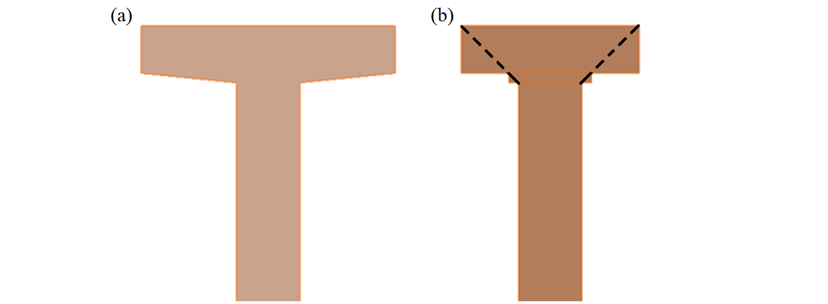
\[ \textsf{\textit{\footnotesize{Fig. 11\qquad Width reduction of a cross-section: (a) user input; (b) FE model – automatically determined reduced flange width.}}}\]
In the case of haunches lying in the horizontal plane (Fig. 12), each haunch is divided into five sections along its length. Each of these sections is then modeled as a wall with a constant thickness, which is equal to the real thickness in the middle of the respective section.
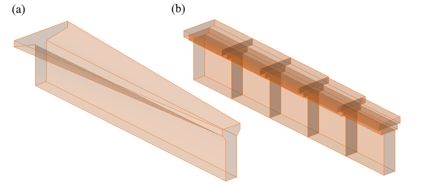
\[ \textsf{\textit{\footnotesize{Fig. 12\qquad Horizontal haunch: (a) user input; (b) FE model – a haunch automatically divided into five sections.}}}\]