Double angle cleat connection
Type of connection: Double angle cleat connection
Unit system: Metric
Designed acc. to: AS 4100
Investigated: Bolts, base metal
Plate material: Grade 300
Bolts: M20 Grade 8.8
Example taken from: B. Kirke, I.H. Al-Jamel. Steel Structures: Design Manual To AS 4100, 2004 – Chapter 9.4.1.1
Geometry
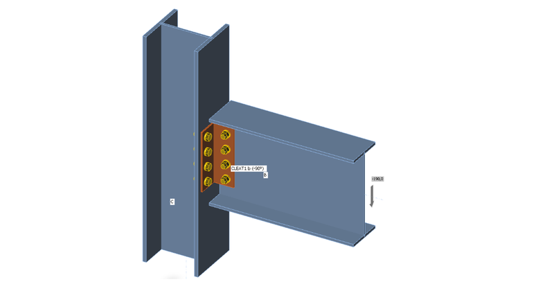
Beam UB 406×178×60 is connected to column UC 254×254×89 by two angles L100×6.
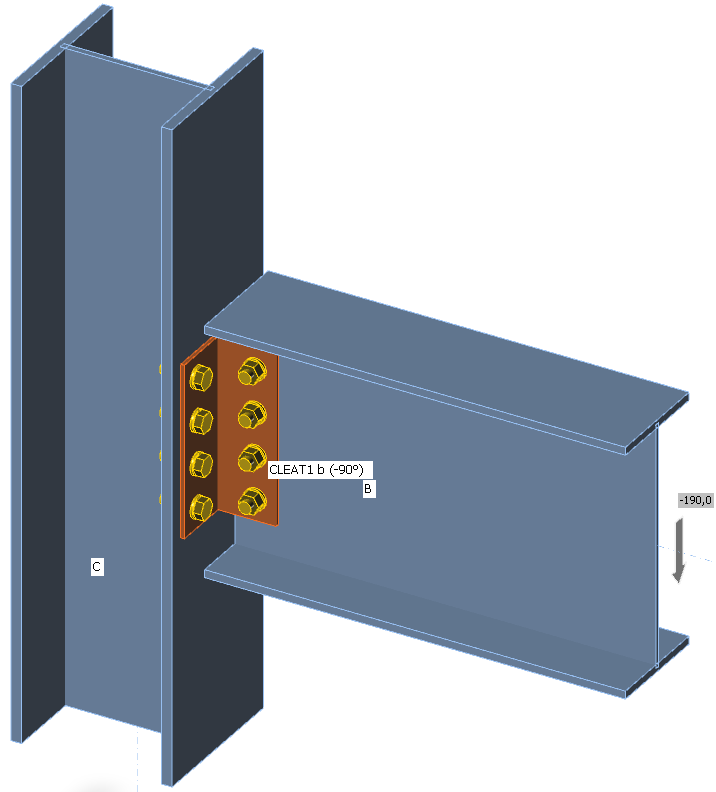
M20 bolts grade 8.8 are selected with the pitch of 70 mm.
Applied load
The beam is loaded by shear force 190 kN. To be conservative, for the design of bolts at the beam web, the shear force should be at the position of the column face so that the group of bolts is loaded also by bending moment – select forces in position 130 mm. For the design of angles and the group of bolts at the column face, the shear force should be applied at the position of centre of gravity of the bolts at the beam web – select forces in bolts.
Comparison between manual calculation and IDEA StatiCa
The results of B. Kirke, I.H. Al-Jamel. Steel Structures: Design Manual To AS 4100, 2004 – Chapter 9.4.1.1 are used as manual calculation.
Connection of web of beam
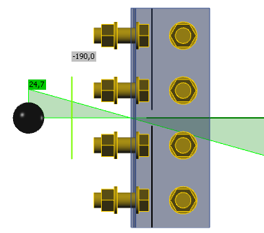
The group of bolts are loaded by the shear force 190 kN and bending moment resulting from the distance between the applied load at the face of the column and the centre of gravity of the bolt group at the beam web, 190 kN × 65 mm = 12.35 kNm. The maximum force in bolt was calculated as 71.1 kN. Results of IDEA is in the figure below. The arrows show the reaction of the plate on the bolt force.
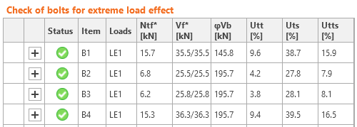
The maximum force is in the bolt B4, each shear plane transfers 36.3 kN, i.e. the whole bolt transfers 2 × 36.3 = 72.6 kN, which closely coincides with the manual calculation.
The bolt resistances use formulas from AS 4100 so that they coincide perfectly, e.g. the bolt shear resistance check (each shear plane is checked separately):
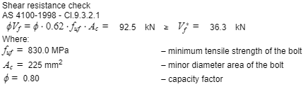
The tearing resistances in manual calculation divides the shear force into components in directions directly towards the ply edge. On the other hand, IDEA StatiCa uses the direction of the vector in the formula. Only the most decisive check is shown for each bolt.
Bolts in IDEA StatiCa are loaded also by small tensile forces due to the deformation of plates. These forces are neglected in manual calculation.
Connection to column flange
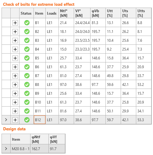
For the check of bolts at the column flange, the force is applied at the centre of gravity of bolts at the beam web. The bolts are loaded by significant tensile force and this is also decisive for the deformation of the angles. Plastic strain is shown in the figure below. The limit plastic strain is 5 % according to European code EN 1993-1-5.
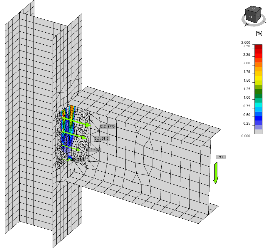
The maximal tensile force is in the upper row of bolts, B8 and B12. Notice the decrease in shear forces of bolts B1–B4 which are loaded only by the shear force and no bending moment. The shear forces in bolts B5–B12 are higher than according to manual calculation: Vf* = 190 / 8 = 23.75 kN. This difference is caused by significant deformation of the angles, which also causes the inclination of shear forces.
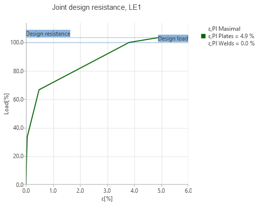
Joint design resistance
The reserve in the load resistance can be seen by the joint design resistance type of analysis. Due to the yielding of angles, the reserve is low. The joint would fail at load factor 103.4 %, i.e. shear force Vf* = 196.5 kN.
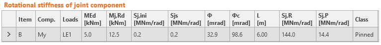
Stiffness
The stiffness of the connection can be determined by setting the type of analysis to "Stiffness", setting the beam as the analyzed member, and setting the correct "Theoretical length" of analyzed member (usually the beam span, centre to centre of columns). The software calculates the secant stiffness at the set load and the initial stiffness at 2/3 Mj,Rd, up to which the moment–rotation diagram is assumed linear. The joint is classified according to the initial stiffness Sj,ini.
Conclusion
IDEA StatiCa Connection provides similar results to the manual calculation. It requires engineering judgement in determining the position of shear load but all checks are performed quickly and automatically. The forces in bolts are affected by the deformation of plates and the difference may be significant if plates are yielding. The forces acting on components are for this reason generally higher than according to manual calculation with the assumption of small deformations.