Structural design of a concrete beam with an opening (EN)
1 New project

Start a New project in IDEA StatiCa Detail.
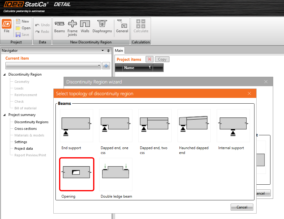
In the Discontinuity Region Wizard, set the concrete and reinforcement grade and define the Concrete cover thickness. Select the Beams template.

Select the topology of the discontinuity region – Opening.
2 Geometry
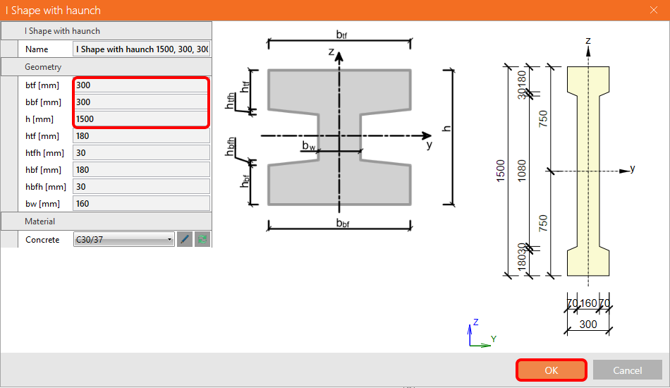
Start the definition of Geometry by changing the cross-section of the M1 beam.

Define the I shape with haunched flanges.

Change the width of the flanges and the height of the beam.
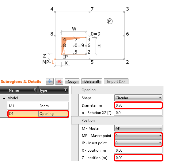
The opening is enlarged and shifted to the center of the beam.
- Read more about the geometry definition in Geometry types in Detail
3 Load effects
Now, move to define the Load of the detail. You can see that two load cases and three combinations were already created. Change the content of the load cases a little bit.

For LC1 (permanent load), change the Internal forces so that you input the values of shear force and bending moment at the point of the opening.

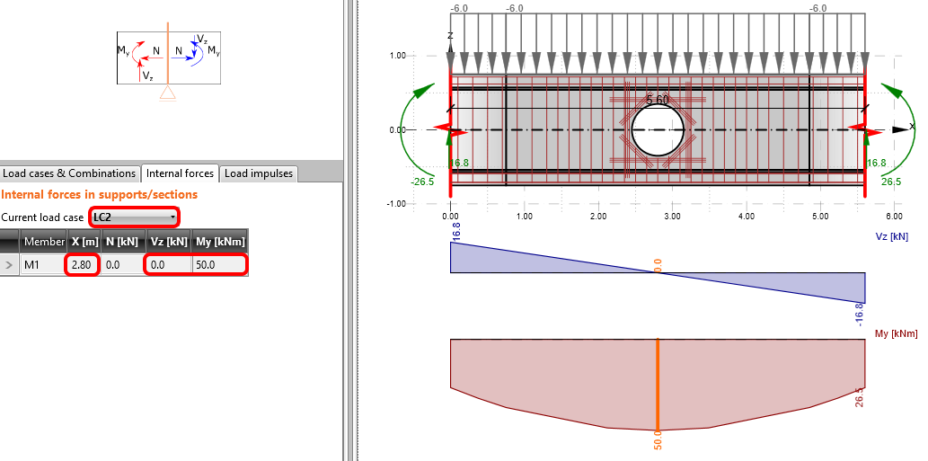
Similarly, change the values of internal forces for LC2 (variable load).
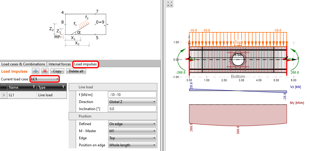
In Load Impulses, keep the value of line load to -10 kN/m in global Z-direction for LC1.
In Load impulses of LC2, change the value to -5 kN/m in global Z-direction.

The nonlinear combinations were already defined: C1 stands for ULS checks. C2 is a quasi-permanent and C3 a characteristic load combination, both defined for SLS code checks (see the tab Load cases & Combinations). The partial coefficients for the combination rules can be adjusted as well.
As you do not need to evaluate the individual load cases, they are unchecked which implies that they will not be analyzed. The calculations will be performed only for the checked items (combinations C1, C2, and C3).

- Learn more about internal forces in General description of Load impulses in Detail application
- Learn more about load impulses in Internal forces and equilibrium in Detail application
4 Reinforcement
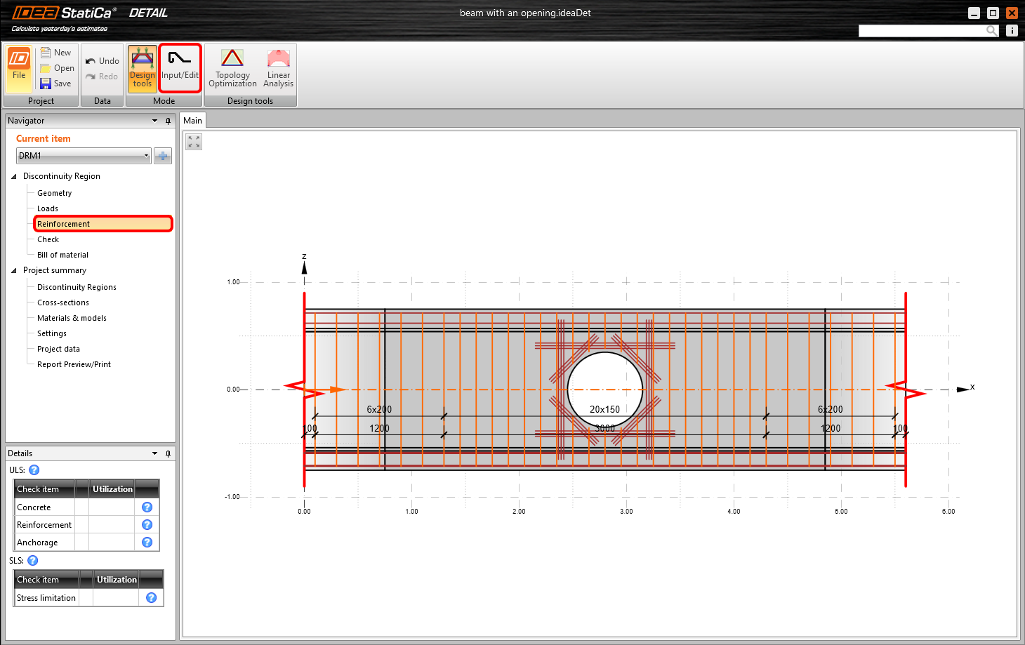
Once the load has been defined, you can proceed to Input/Edit the reinforcement. You will exploit the items created by the template.
You can change the diameter of stirrups and adjust their distances (the first value corresponds to the distance of the first stirrup from the edge, the other stirrups will be distributed in distances given by the second value).

Reduce the diameter of bars of reinforcement RO1 around the opening and the number of layers of horizontal/vertical and diagonal bars. Change the distance between horizontal/vertical bars and also adjust the length of the diagonal bars and anchoring of horizontal/vertical bars.

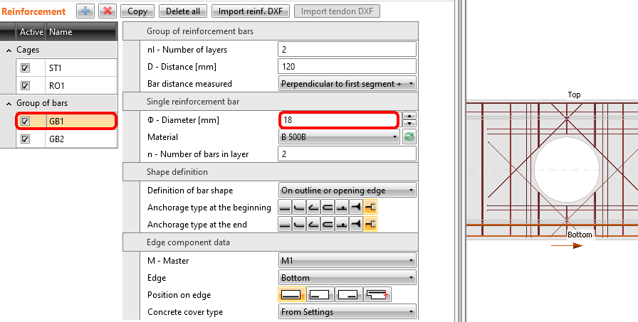
The operation GB1 includes a group of bars at the bottom face of the beam. Change the diameter of bars.
- Master your reinforcing skills by reading Reinforcement definition in the Detail application
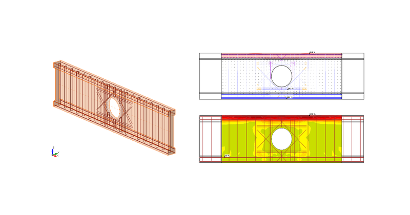
5 Calculation and Check
Proceed to calculate the project. Continue to Check in the navigator and press the Calculate button at the top ribbon.

In the left bottom table, you can see the overview of all the code checks and the status of the checks (passed/failed).
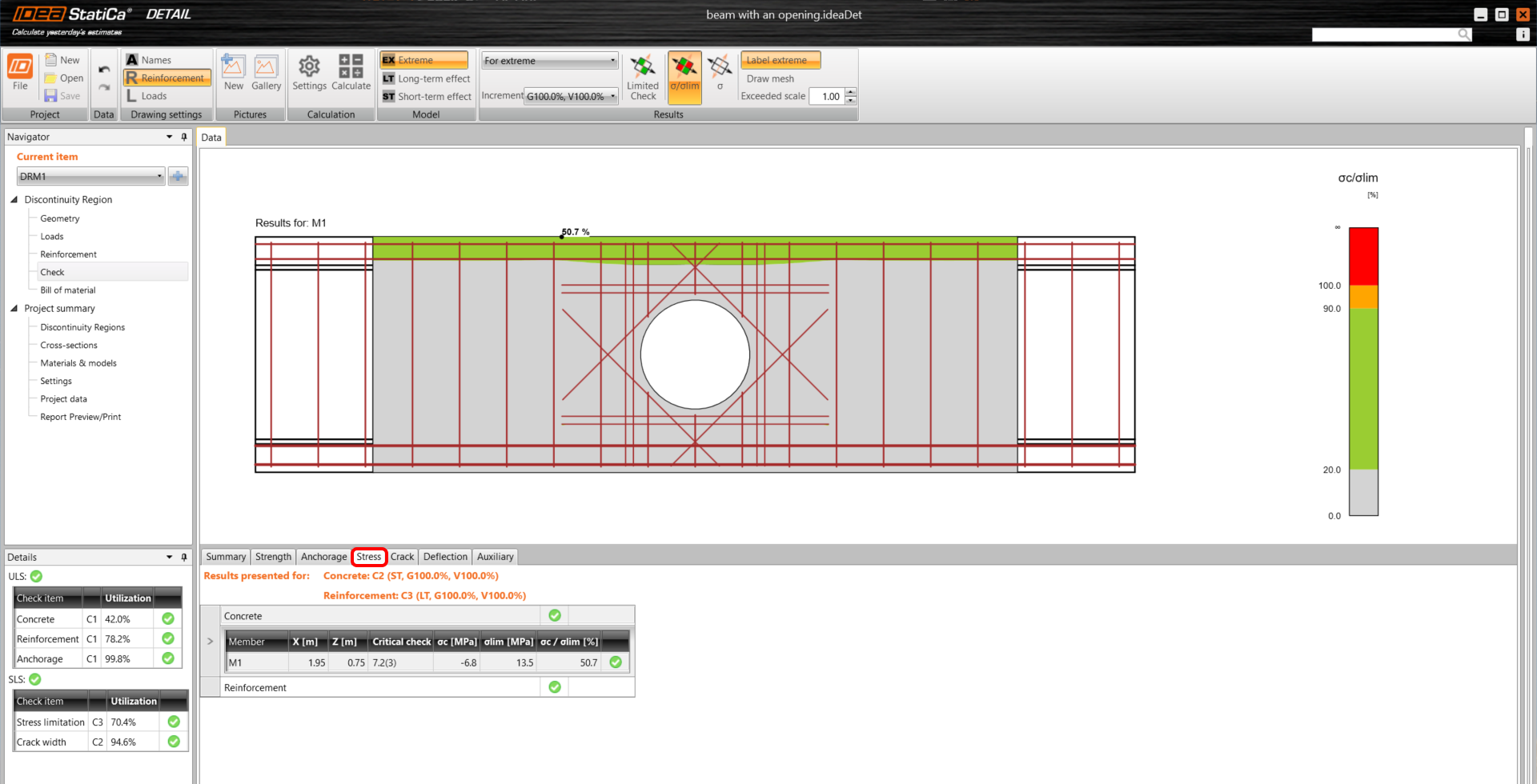
In the table in the middle, all the detailed results can be found. At the moment, the resulting strength check of the concrete in ULS is presented. In the top ribbon, the limit value for the diagram can be changed. You changed the value so that only the concrete in compression over -2 MPa is marked red.
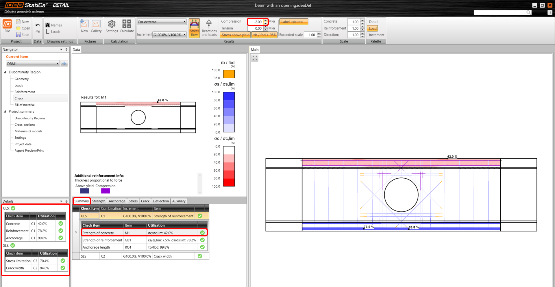
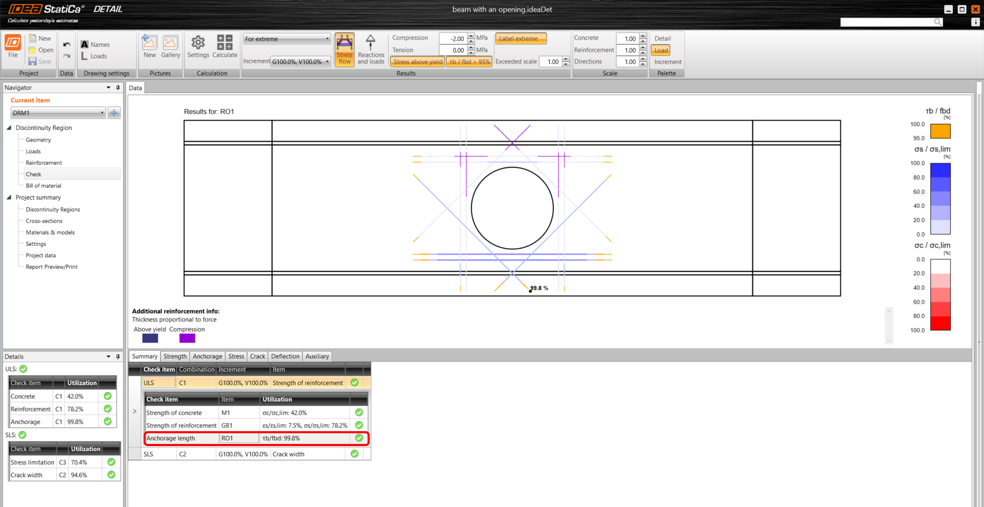
By changing the top tabs, you can display all the code checks. In the Summary, the main results for ULS/SLS are presented. Click on the line in ULS/Anchorage length to display the utilization of the bond between concrete and reinforcement (with the most critical spot marked in the figure).
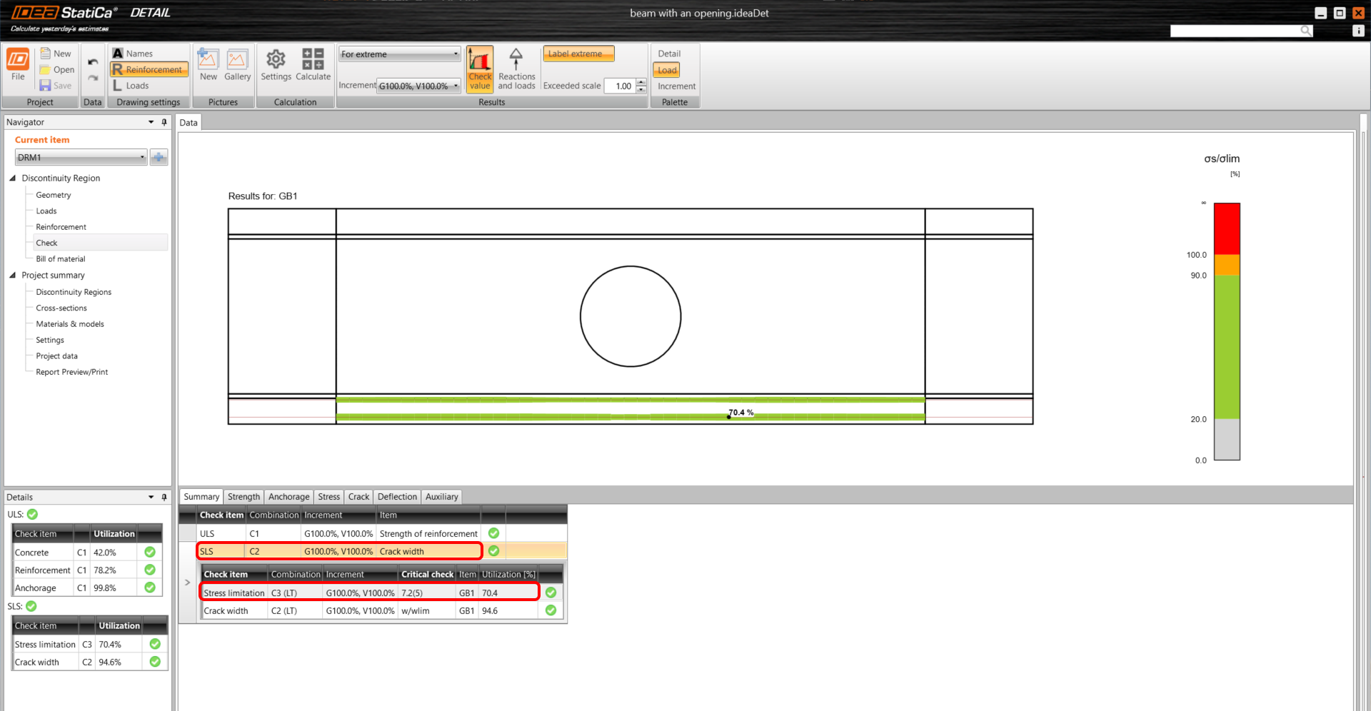
We open the SLS results by selecting, e.g., the line SLS/Stress limitation line in the table.
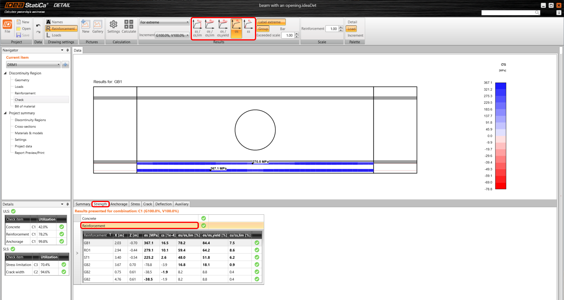
To open the detailed results of ULS, change the tab to Strength. As noted above the table, C1 combination was used to check ULS.
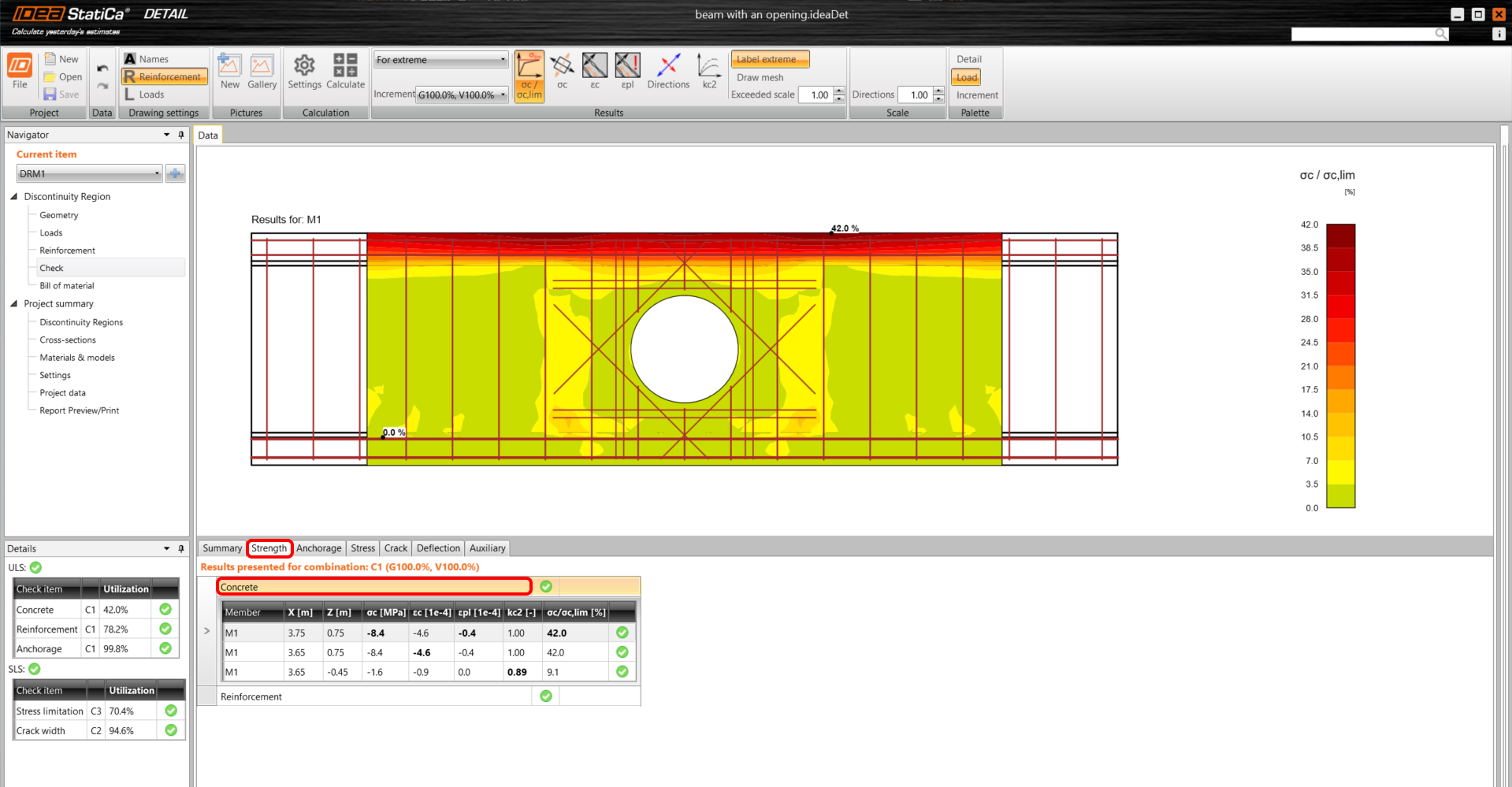
Again, you can display the results for Concrete and also for Reinforcement by selecting the corresponding line in the table. You can select any bar of reinforcement to see its results of analysis and code check.
- More info about ULS results can be found in General description of ULS results in Detail application
The results of SLS are located in the tabs Stress, Crack, and Deflection. For the Stress limitation state, the C2 combination was governing to check the concrete, while C3 to check the reinforcement.
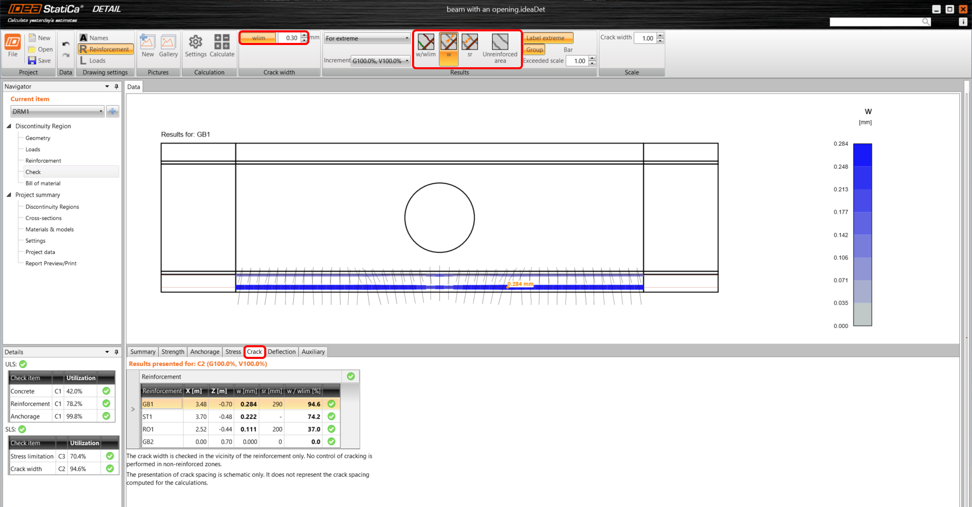
Calculated crack widths can be displayed in the Crack tab (combination C2). The calculated values are compared to the limit value w_{st,lim} that can be edited in the top ribbon.
- More info about SLS results can be found in General description of SLS results in Detail application
6 Report
At last, go to the Report Preview/Print. IDEA StatiCa offers a fully customizable report to print out or save in an editable format.
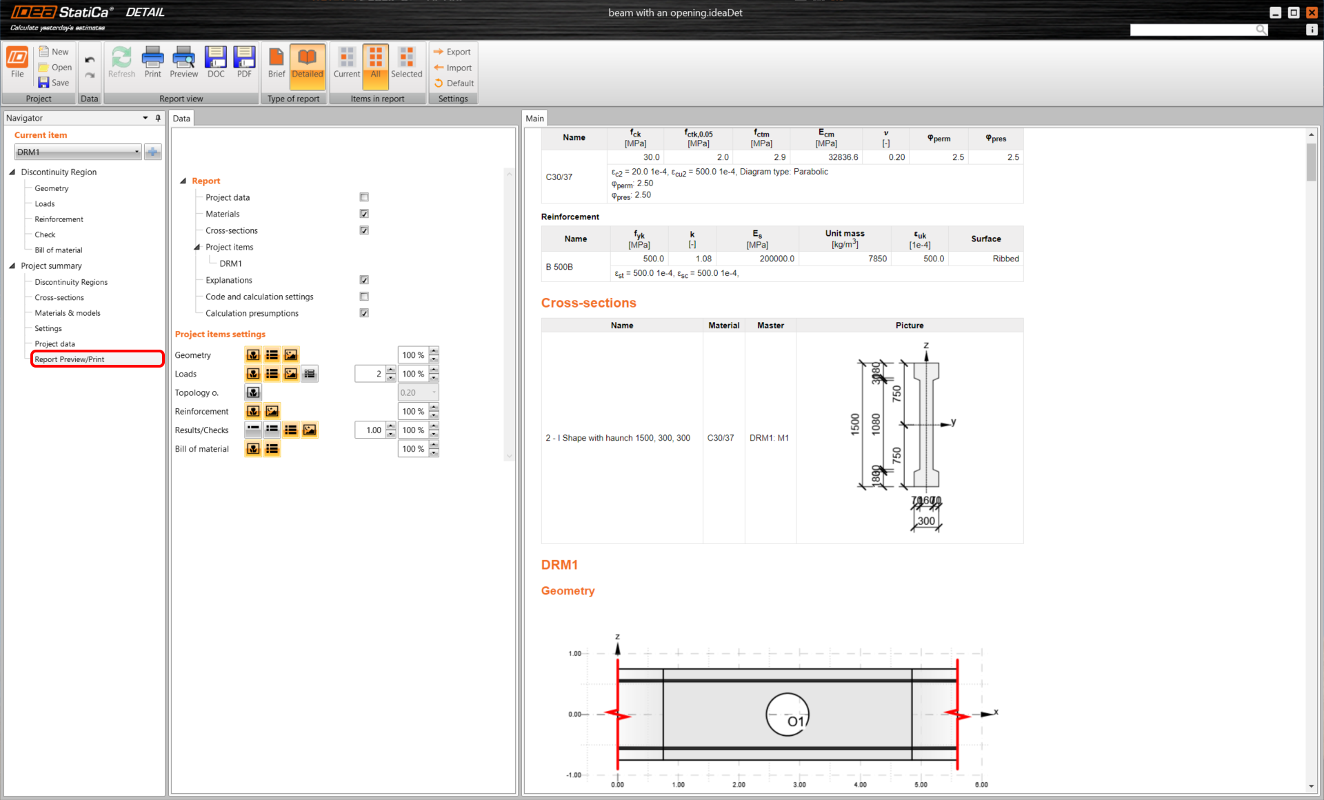

You have designed, optimized, and code-checked the part of the beam with an opening.