Buckling analysis according to AISC
IDEA StatiCa Connection allows users to perform linear buckling analysis to confirm the safety of using plastic analysis. The result of linear buckling analysis is buckling factor αcr corresponding to the buckling mode shape. The buckling factor is the multiplicator of set load when Euler’s critical load of a perfect structure is reached. E.g. elastic critical buckling load Pe is determined by:
- loading a column by compressive force P
- performing linear buckling analysis, selecting most critical buckling mode (usually the first) and buckling factor αcr
- multiplying compressive force by buckling factor, i.e. Pe = P × αcr
AISC codes use mostly critical slenderness to limit thickness of plates. The critical slenderness can be expressed by critical buckling factor using following formulas:
\[ \lambda = KL/r \]
\[ \bar{\lambda_p} = \frac{\lambda}{\pi \cdot \sqrt{\frac{E}{F_y}}} \]
\[ \alpha_{cr} = \frac{\alpha_{ult}}{\bar{\lambda_p} ^2} = \frac{\alpha_{ult}}{\left ( \frac{\lambda}{\pi \cdot \sqrt{\frac{E}{F_y}}} \right )^2} \]
where:
- λ – plate slenderness
- KL – effective length
- r – radius of gyration
- \(\bar{\lambda_p} \) – plate relative slenderness
- \(\alpha_{ult}\) – minimum load amplifier for the design loads to reach the characteristic value of resistance of the most critical cross-section, neglecting any plate buckling and lateral-torsional buckling; for load equal to plate plastic resistance, \(\alpha_{ult} = 1 \)
- E – Young’s modulus of elasticity
- Fy – yield strength
General recommendation
In AISC 360-16 – J.4, it is stated that plastic resistance may be used if λ = KL/r ≤ 25. Then e.g. for steel A36 the corresponding buckling factor is equal to 12.7. Note that for stronger steel, the corresponding buckling factor decreases. That means if the buckling factor is higher than 12.7, plastic resistance may be safely used. If the buckling factor is smaller, provisions of Chapter E apply.
\[ \lambda = 25 \ll \gg \bar{\lambda_p} \cong\frac{25}{\pi \cdot \sqrt{\frac{29000 ksi}{36 ksi}}}=0.28 \]
\[ \alpha_{cr} = \frac{\alpha_{ult}}{\bar{\lambda_p}^2}=\frac{1}{0.28^2} = 12.7 \]
Steel with Fy=50 ksi
\[ \alpha_{cr} = 9.16\]
This limit is very strict and applies generally for all types of plates. It was derived from Dowswell’s research into stability of gusset plates. For gusset plates or connecting plates directly affecting the buckling of connected member, this limit should be used.

Stiffening plates in the joint
However, for plates in the joint, e.g. stiffeners, haunches, column web panel, the limiting buckling factor may be much smaller using the provisions of Chapter E or corresponding chapters in design guides. A few examples are presented:
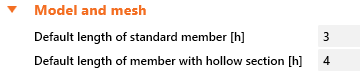
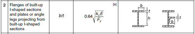
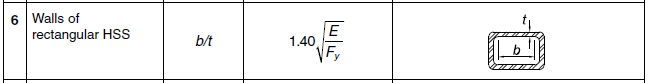
Limiting width to thickness ratio λr from AISC 360-16, Table B4.1a for web of built-up I section, flange of built-up I section and wall of rectangular hollow section:
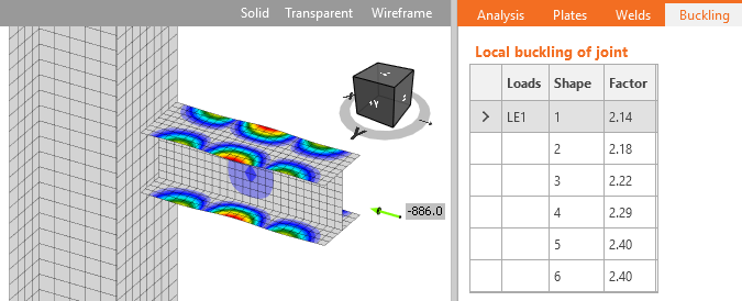
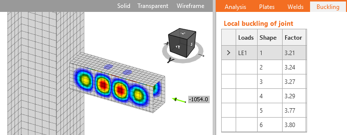
In the software, the length of the standard member was set to 3 and length of the member with hollow section to 4 to enable the development of local buckling. For these examples, the stiff support for investigated members is necessary and therefore, the strong column fixed on both ends was used. The limiting width-to-thickness ratio is set to the investigated plate. The member is loaded to its compressive resistance. The buckling analysis is performed and the lowest buckling factor corresponding to the buckling mode shape for the investigated plate is noted. Other plates in the model are thick so the first buckling mode is relevant. The plate is considered non-slender and its full width can be used. Higher plate thickness leads to a higher buckling factor.
| E = | 200000 | MPa | Young's modulus of elasticity | |
| Fy = | 223.38 | MPa | yield strength | |
| Fcr = | 223.38 | MPa | critical stress | E3 or E4 |
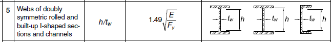
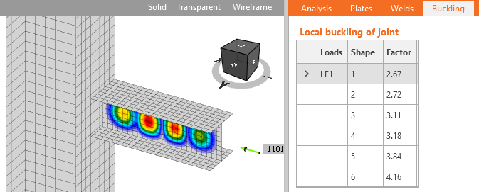
Web of built-up I section
| h = | 180 | mm | width of the element | |
| tw = | 4.1 | mm | thickness | |
| h/tw = | 43.9 | width-to-thickness ratio for the element | B4.1 | |
| λr = | 44.6 | limiting width-to-thickness ratio | Table B4.1a |
Flange of built-up I section
| b = | 95 | mm | width of the element | |
| t = | 4.7 | mm | thickness | |
| b/t = | 20.2 | width-to-thickness ratio for the element | B4.1 | |
| λr = | 19.4 | limiting width-to-thickness ratio | Table B4.1a |
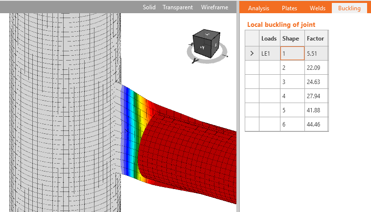
Wall of RHS
| b = | 180 | mm | width of the element | |
| t = | 4.3 | mm | thickness | |
| b/t = | 41.9 | width-to-thickness ratio for the element | B4.1 | |
| λr = | 41.9 | limiting width-to-thickness ratio | Table B4.1a |
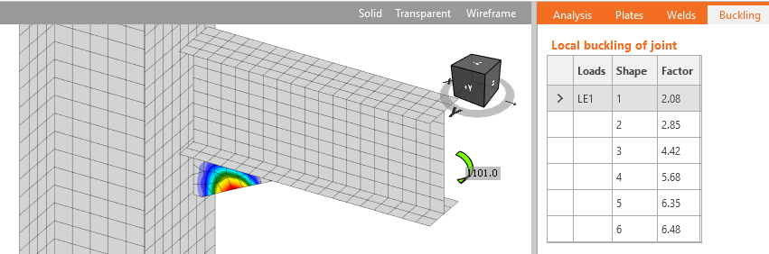
Triangular haunch
Thickness limitation according to AISC DG4 - 3.16 and AISC 358-18 – 6.8.1 – Step 9:
The beam was loaded by a bending moment so that the plate was at its limit compressive strength and then performing linear buckling analysis.
End plate stiffener
| hst = | 140 | mm | stiffener height | |
| ts = | 8.4 | mm | stiffener thickness | AISC DG4 - 3.16 |
\[ \frac{h_{st}}{t_s} \le 0.56 \sqrt{\frac{E}{F_{ys}}} \, \textrm{or} \, t_s \ge 1.79 h_{st} \sqrt{\frac{F_{ys}}{E}} \qquad \textrm{(3.16)} \]
The limits in AISC codes correspond for these examples to buckling factor around 3. For experimental research into slender compressed plates in connection see the research papers.
Conclusion
Linear buckling analysis should be performed if buckling of plates is a possibility in the connection. According to AISC 360-16 – J.4, stability of plates in connections is ensured if slenderness λ ≤ 25, which corresponds to buckling factor αcr = 13 for 36 ksi yield strenght plates and αcr = 9.16 for 50 ksi. If buckling factor is over 13 no further buckling checks are necessary and plastic analysis may be used without reservations.
For plates connecting individual members, e.g. gusset plates, the limit from AISC 360-16 – J.4, αcr ≥ 13, should be used. For stiffening plates in the joint, e.g. stiffeners, ribs, short haunches, the limit of buckling factor may be considered αcr ≥ 3.
It is still possible to design a joint with smaller buckling factor but buckling checks must be performed by hand or by geometrically nonlinear analysis with imperfections.
References
AISC. (2016). Specification for Structural Steel Buildings. American Institute of Steel Construction, Chicago, Illinois.
Dowswell, B. (2006), Effective Length Factors for Gusset Plate Buckling, Engineering Journal, AISC, Vol. 43, No. 2, pp. 91–101.