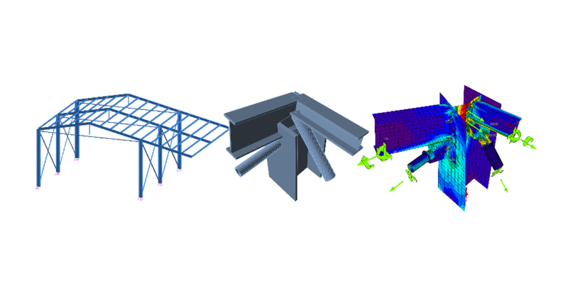
Advance Design BIM link for the structural design of a steel connection (EN)
1 How to activate the link
- Download and install (as administrator) the latest version of IDEA StatiCa
- Make sure that you are using the supported version of Advance Design
- I necessary please install Microsoft Access Database Engine 2016 x64 version
After installation of both programs, run IDEA StatiCa and start with the item BIM. In the BIM wizard, continue with the item Activate your BIM Link. During the process notification "Run as administrator" appears. Please confirm with the button Yes.

Select the Advance Design and click the button Install. The process of integration will start.

2 How to use the link
Open the attached project in Advance Design.
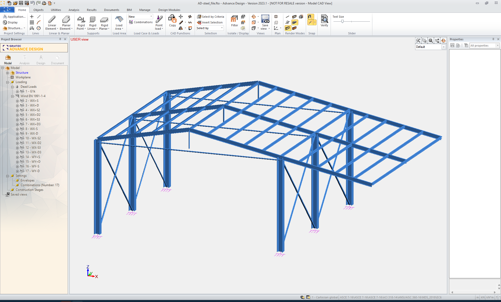
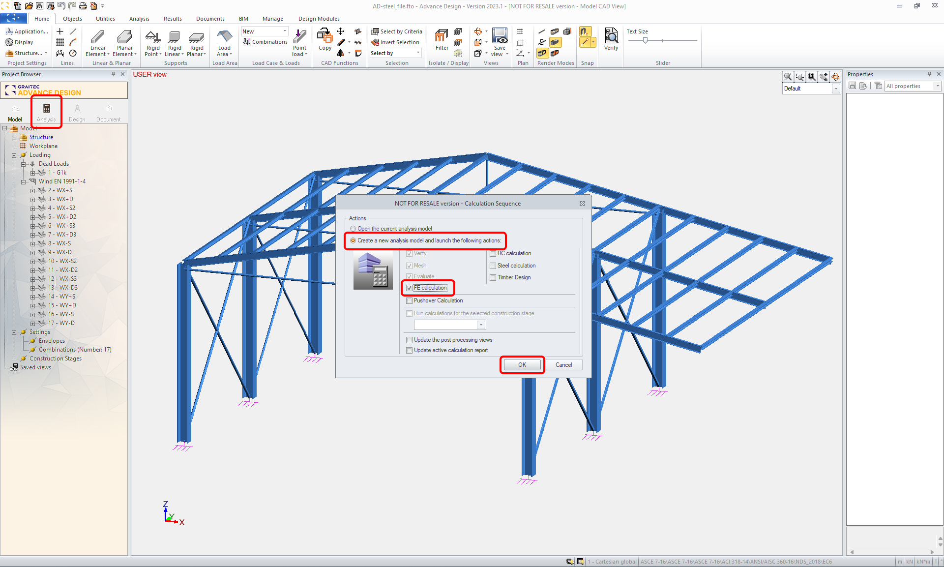
You have to run the FEM analysis.
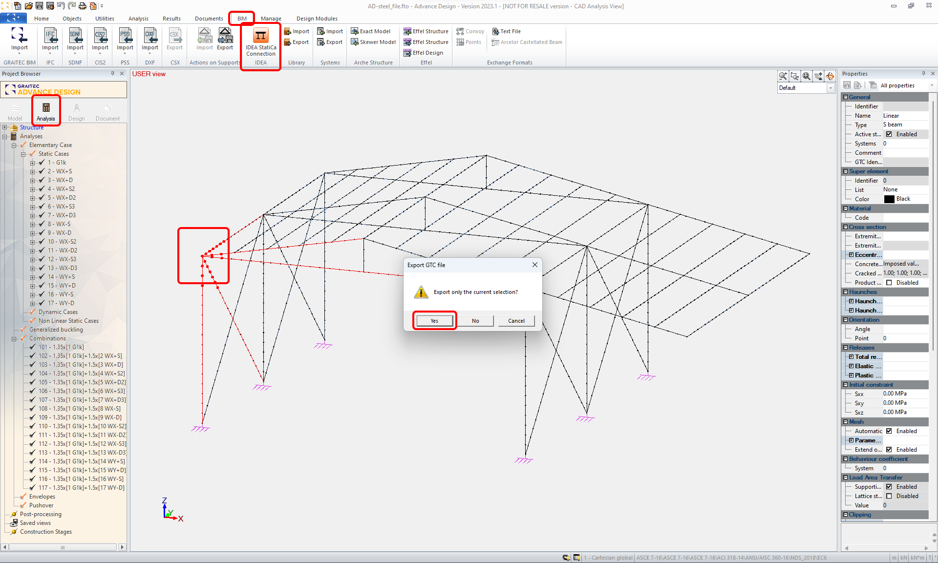
When the results appear, select the right node with all related members and export it by ADC command in the top ribbon.
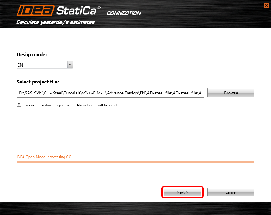
The import wizard automatically appears. Check the Overwrite the existing project and Next.

Continue with the Next command button.

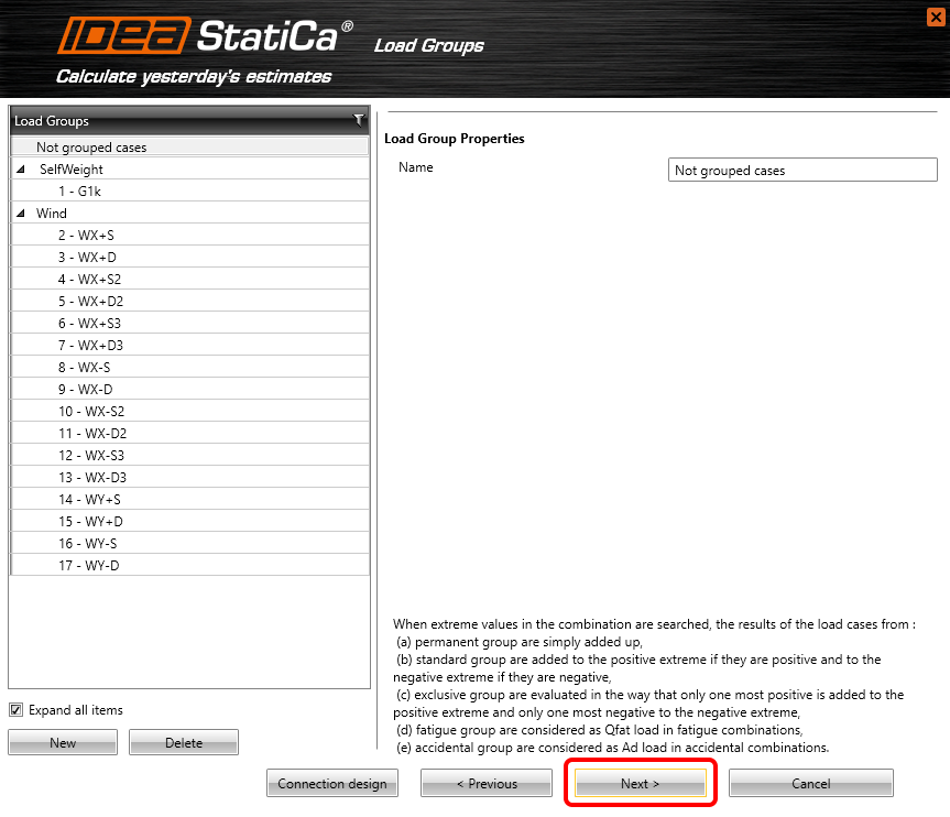
You can see the imported Load Groups. Let’s continue with the Next command button.
You can see the imported Combinations. Let’s continue with the Next command button.

You can see the imported Result Classes. Let’s continue with the Finish command button.

3 Design
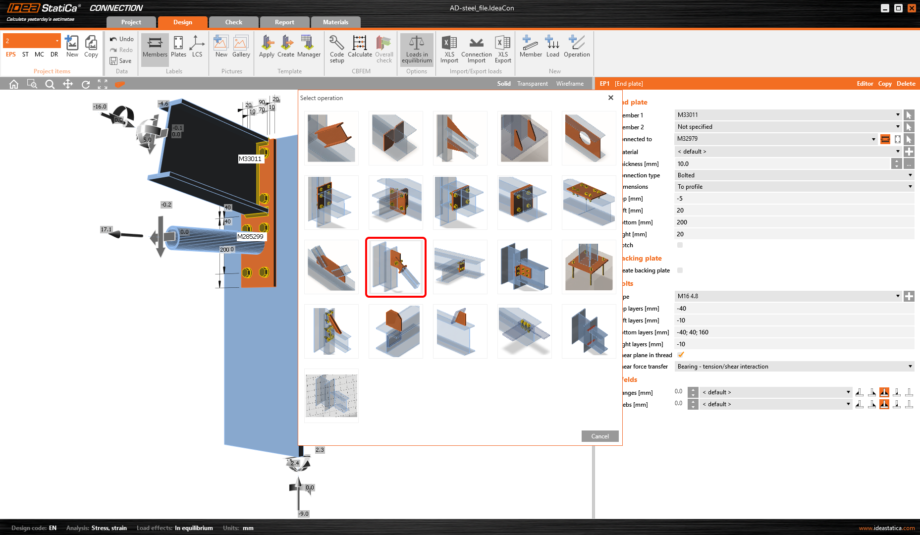
Automatic data transfer is finished and IDEA StatiCa Connection with the generated project is launched. All members and load effects were added automatically.
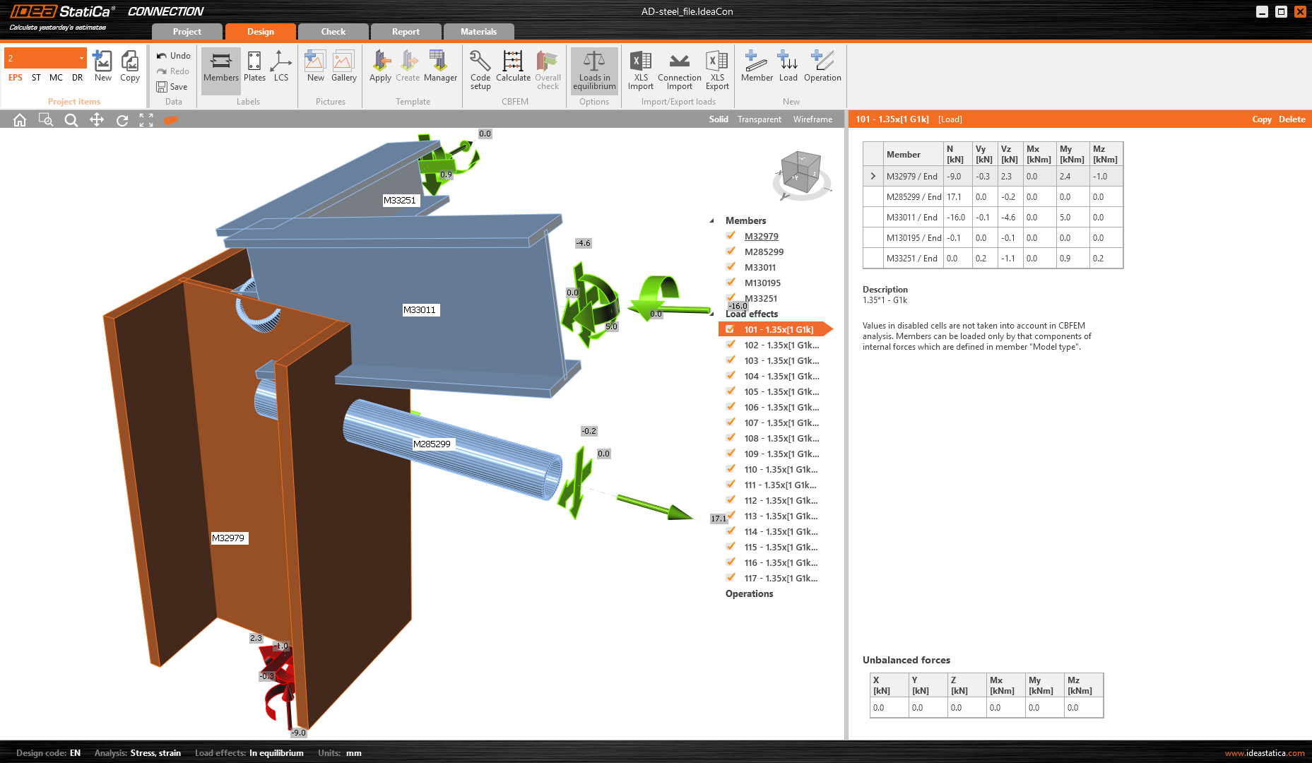
In the first step, you have to change the Model type for the tube members to N-Vy-Vz only. The bracing members will be connected as a hinge truss connection so let’s prevent it from rotating. Also, it is a good step to put the forces into the Bolts. You ensure that the hinge will behave well by this step.

And for the second member.

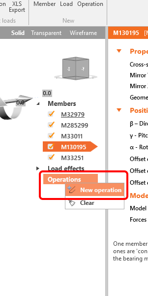
You have to define the right manufacturing operation. Let’s start with the right mouse button click on the Operations and select the New operation.
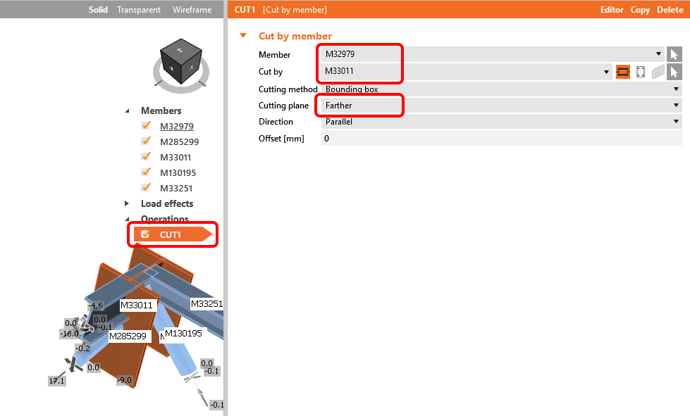
The first manufacturing operation will be the Cut of a member.

Change the properties of the operation CUT1 according to the picture below.
In the next step, use again the right-click on Operation and add the manufacturing operation Endplate and fill in the values below.

In the next step, add another new manufacturing operation Connecting plate.
And adjust the properties according to the picture below.

Let’s continue with creating new manufacturing operation Endplate and change the properties according to the picture below.

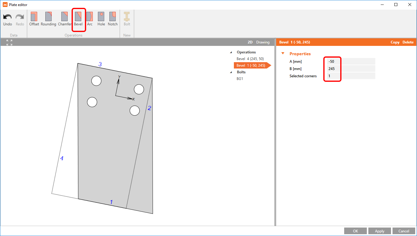
After that, you need to change the shape of the endplate itself. For this, the Editor is the right tool.

In the Plate editor, you can change the shape of the plate and arrange the bolt pattern. Let’s change the shape first. You have to add a Bevel.

And the second Bevel will make the plate equal.
Now change the bolt pattern. Let’s click to the Bolts at the tree of entities to the 2D scene and then add two more bolts by the top ribbon Bolt command. You have to Explode the bolt pattern to change the X and Y coordinates according to the picture below.
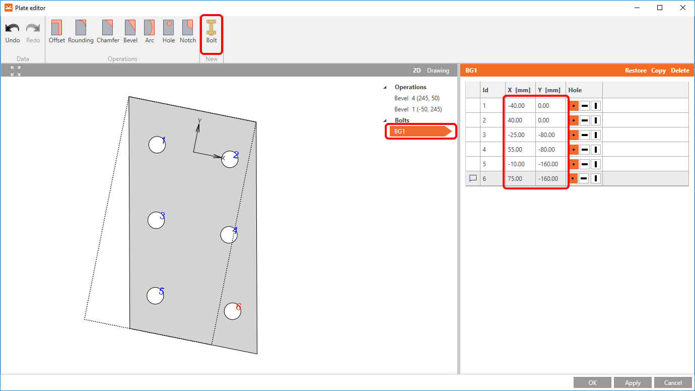
The well designed EP2 manufacturing operation with the right shape of the endplate should look like the one in the picture below.

The next step is the operation Connecting plate for the last bracing tube member. After adding it you have to change the properties according to the picture below.

You want to chamfer the gusset plate. You will do it by the Editor tool.

Let’s add one Chamfer.

The last step needed to finish the design of the joint is the Plate cut. Let’s add it and change the properties of PCUT1 according to the picture below.

4 Calculation and Check
You can calculate the analysis right in the Design tab by the Calculate command.

After a while, the results summary will appear in the left top corner of the 3D scene and the Overall check model view is set. You can quickly fine-tune the model in case you are not satisfied.

You will choose the Check tab and turn on the Equivalent stress, Mesh, and Deformed model view. You can explore the detailed results for the Bolts also, let’s expand the results for the bolt B15.

5 Report
At last, go to the tab Report. IDEA StatiCa offers a fully customizable report to print out or save in an editable format.

6 Update
You can take advantage of the Update function. With this function, you can keep all manufacturing operations and perform the export from Advance Design again.
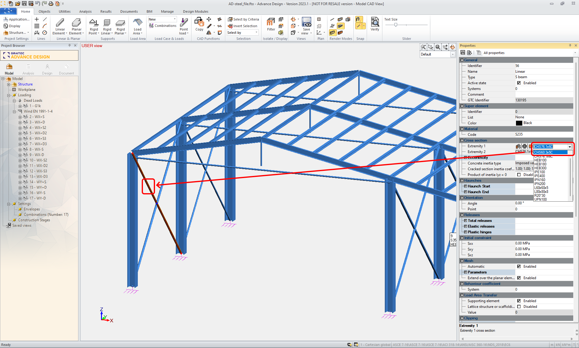
Let’s say you need to change some entities in the Advance Design model. For example, the cross-section of the bracing because it didn’t pass the code check. You change the cross-section to the CHS 60.3x5C. You can change the load also.
You need to recalculate the project. Then you export the same joint.
In the Connection wizard window, you confirm with the Next command button. You don’t want to overwrite your previous work, so you keep the checkbox Overwrite existing project unchecked.
Now let's proceed with the Connection design command button.

After a while the IDEA StatiCa Connection project window appears, all Manufacturing operations remain from the previously saved project and the cross-section of the bracing member was updated to the CHS60.3/5.0. You can perform the code-check analysis again.
