CBFEM Weld Model: Validation and Verification
Several options for treating welds in numerical models exist. Large deformations make the mechanical analysis more complex and it is possible to use different mesh descriptions, different kinetic and kinematic variables, and constitutive models. The different types of geometric 2D and 3D models and thereby finite elements with their applicability for different accuracy levels are generally used. Most often used material model is the common rate-independent plasticity model based on von Mises yield criterion. Two approaches which are used for welds are described.
Direct connection of plates
The first option of weld model between plates is a direct merge of meshes as shown in Figure 1. The load is transmitted through a force-deformation constrains based on Lagrangian formulation to opposite plate. The connection is called multi-point constraint (MPC) and relates the finite element nodes of one plate edge to another plate. The finite element nodes are not connected directly. The advantage of this approach is the ability to connect meshes with different densities. The constraint allows to model mid-line surface of the connected plates with the offset, which respects the real plate thickness. This type of connection is used for full penetration butt welds.
Weld with plastic redistribution of stress
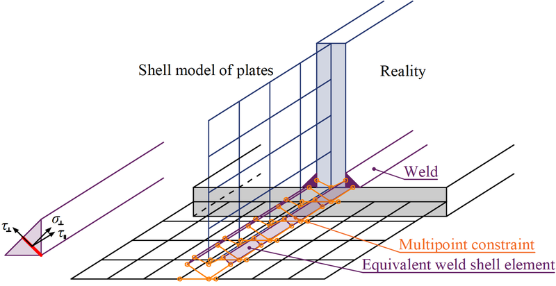
The load distribution in the weld is derived from the MPC, so the stresses are calculated in the throat section. This is important for the stress distribution in the plate under the weld and for modeling of T-stubs. This model does not respect the stiffness of the weld and the stress distribution is conservative. Stress peaks, which appear at the end of plate edges, in corners and rounding, govern the resistance along the whole length of the weld. To express the weld behavior an improved weld model is applied. A special elastoplastic element is added between the plates. The element respects the weld throat thickness, position and orientation. The equivalent weld solid is inserted with the corresponding weld dimensions as shown in Figure 2. The nonlinear material analysis is applied and elastoplastic behavior in equivalent weld solid is considered. The stress peaks are redistributed along the weld length.

Figure 1: Constraint between mesh nodes (butt weld)
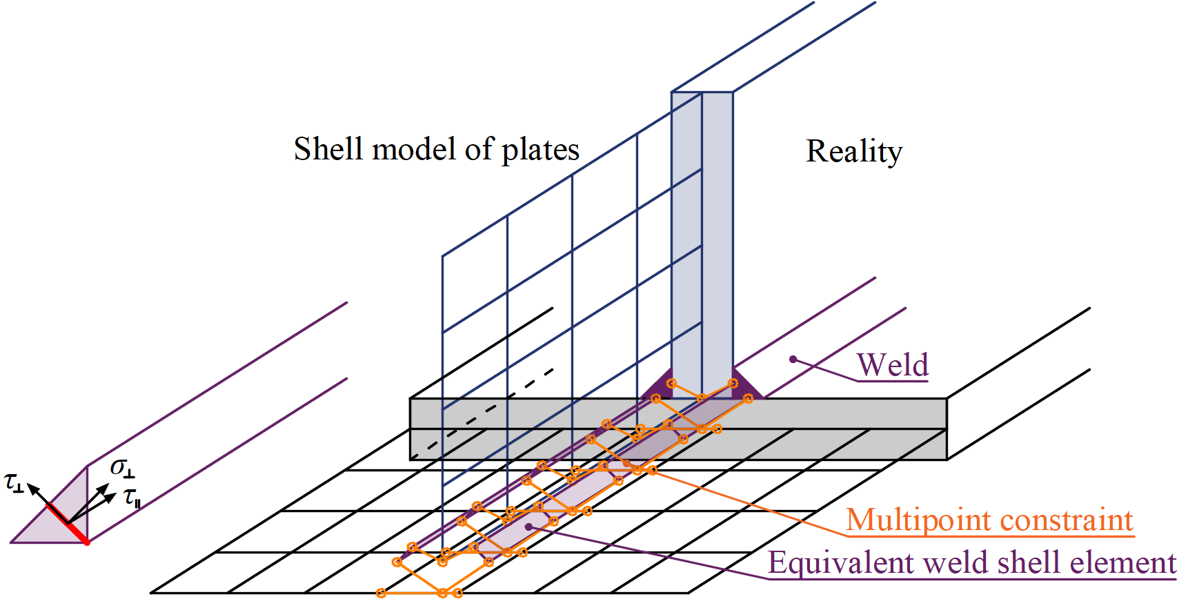
Figure 2: Constraint between weld element and mesh nodes (fillet weld)
The aim of design weld models is not to capture reality perfectly. Residual stresses or weld shrinkage are neglected. The design weld models are verified for their resistance according to relevant codes. For each code an appropriate design weld model is selected. The resistances of the regular welds, welds to unstiffened flange, long welds, and multi-oriented weld groups were investigated to select parameters of the design weld element.
The plastic strain is 5% of the weld throat thickness and it confirms with the maximum plastic strain of plates.
Verification
Comparison to EN 1993-1-8
The presented model for CBFEM is verified on a fillet weld in a lap joint and weld to unstiffened flange with analytical model presented in EN1993-1-8:2005. For lap joint, two plates, P10 and P20, are connected to each other in three configurations: with a transverse weld, with a longitudinal weld, and combination of the transverse and longitudinal welds, see Figure 3 (Wald et al, 2019). The length (100–800 mm) and throat thickness (3–10 mm) of the weld are the changing parameters in the study. The study covers long welds whose resistance is reduced due to stress concentration. The joint is loaded by normal force only. The summary of results is presented in Figure 4. It shows that the difference of the two calculation methods is in all cases less than 7 %.

Figure 3: Configurations for sensitivity study, with a transverse weld, with a longitudinal weld and combination of both (not shown)

Figure 4: Verification of CBFEM prediction of fillet weld in a lap joint with analytical model in EN1993-1-8:2005
A fillet weld connecting a plate perpendicular to an unstiffened plate is studied. The CBFEM model is verified to analytical model based on effective width beff in Cl. 4.1 in EN 1993-1-8:2005. The plate is connected to open and box section columns and loaded in tension. The flanges of HEB160 till HEB260 are studied. They are connected with plates of width 160–260 mm by welds with the throat thickness of 3 mm. The box section consisting of two channel sections is studied for 200 mm width and 5–11 mm thicknesses, see Figure 5 (Wald et al, 2019). The results of this sensitivity study are presented in Figure 6. Results of CBFEM are compared with the results of the analytical model and very good agreement is observed. The difference is for all load cases less than 10 %.

Figure 5: Studied fillet weld connections of a flexible plate to a) an unstiffened column flange of open section and b) an unstiffened box section

Figure 6: Verification of CBFEM prediction of a fillet weld connecting a plate perpendicular to an unstiffened plate with analytical model in EN1993-1-8:2005
Comparison to AISC 360-10
AISC 360-10, Section J2-4 contains a model for strain compatibility of welds. Longitudinal welds develop the highest strain at fracture, also the peak load resistance is reached at much higher strain than in the case of transverse welds; see Figure 7. If a weld group with both transverse and longitudinal welds is loaded, the transverse welds may fracture before the longitudinal welds reach their maximum capacity. Therefore, it is important to check the strain compatibility of welds if the maximum weld load resistance is estimated in the design.

Figure 7: Comparison of the proposed elastoplastic model of weld to experiments (Callele et al., 2005)
The code uses empirical formulas for deformation of weld element. The formulas for deformation of weld element at maximum stress Δm and at fracture Δu are shown below:
Δm = 0.209 (θ + 2)-0.32 w
Δu = 1.087 (θ + 6)-0.65 w ≤ 0.17 w
where w is the weld size and θ is the angle between the longitudinal axis of weld element and the direction of the resultant force acting on the element in degrees. The weld deformation is in dependence on the loading angle θ and weld size is plotted in Figure 8. Using the throat thickness as a reference dimension of the weld, the model in AISC code has a strain ranging between 7 % for transverse weld and 24 % for longitudinal weld. The CBFEM model uses a constant value of strain 5 % and is therefore safer than the AISC weld model.

Figure 8: Weld deformation at maximum stress and at fracture in dependence on the loading angle (on the left) and weld size for longitudinal and transverse weld (on the right)
Comparison to CSA S16-14
The strain compatibility is worked out in detail in CSA S16-14. The resistance of a weld in a group of multi-oriented welds is multiplied by a reduction factor:
\[ M_w = \frac{0.85 + \theta_1/600}{0.85 + \theta_2/600} \]
where θ1 is orientation of the weld segment under consideration and θ2 is orientation of the weld segment in the joint that is nearest to 90°. The highest reduction is for a group of longitudinal and a transverse weld – 15 % for the longitudinal weld, which equals to the reduction in AISC 360.
The resistance of multi-oriented weld groups is checked by calculation according to AISC and CSA for the specimens from research by Callele et al. (2005). The resistances of the multi-oriented weld groups are nearly identical; the biggest difference between CBFEM weld model and code calculation is 1.3 %. In Table 1, also the results of only transverse (labeled t) and longitudinal (or angled at 45° – labeled l) are provided. In CBFEM, the value of Mw can be recalculated as 0.83 for a group of transverse and longitudinal weld which is very close to 0.85 from the code. However, for a group of transverse and inclined weld at 45°, the Mw = 0.98 in CBFEM compared to 0.925 from CSA code.

Table 1: Comparison of the CBFEM weld model to calculation according to AISC 360 and CSA S16-14 for multi-oriented weld groups
Validation
The validation of the proposed CBFEM model is presented on three published experimental works for the fillet welds:
- Loaded in parallel (Kleiner, 2018)
- Loaded perpendicularly (Ng et al, 2002)
- Multi-oriented welds (Callele et al, 2005)
Longitudinal welds (loaded in parallel) were tested intensively at University of Stuttgart. All tested welds have relatively large plastic branch although even welds of high strength steel with incompatible welding electrodes were tested. The weld model used in CBFEM is very conservative both in terms of resistance and plastic deformation; see Figure 9 for an example with one welding electrode type.

Figure 9: Comparison of the proposed elastoplastic model of weld to experiments (Kleiner, 2018) for longitudinal welds on the stress–deformation diagram
Transverse welds (loaded perpendicularly) were tested at University of Alberta. Lapped splice and cruciform specimens were tested in various temperatures. The resistance of all tested welds was conservative in all cases compared to both AISC and CSA code and thus also for CBFEM weld model which respects the resistance of welds according to the national codes. The deformation capacity of transverse welds is significantly lower, especially for cruciform welds. Unfortunately, cruciform welds contained only 6 specimens. It is not stated in the report whether used steel had sufficient through-thickness material properties, i.e. value ZRd from EN 1993-1-10. A vast amount of lapped splice joints were tested with variable weld metal classification and manufacturer, base metal steel fabricator, nominal weld size, and test temperature. All tested lapped splice joints had higher deformation capacity than the suggested weld model in CBFEM; see Figure 10.
Figure 10: Comparison of the proposed elastoplastic model of weld to experiments with lapped splice joints (Ng et al, 2002) for transverse welds on strain at fracture
Multi-oriented weld groups were tested again at University of Alberta (Callele et al., 2005). Welding electrodes E70T-7 (480 MPa nominal tensile strength) with 12 mm and 8 mm (notation a) weld size. Steel grade A572, Gr. 50 was used for base metal. Transverse and longitudinal welds are labeled TL (11 specimens) and transverse and inclined by 45° are labeled TF (8 specimens). The resistance of the weld group is in all cases much larger than analytical solution and CBFEM weld model; see Figure 11. This is caused by higher strength of the weld, larger fracture area, and used safety factor. Nominal weld dimensions and strength were used in the CBFEM model. Deformation at fracture is always very close to the deformation at maximum load. In all cases but one (specimen TF4), CBFEM weld model has lower deformation.

Figure 11: Comparison of the proposed elastoplastic model of weld to experiments with multi-oriented weld groups (Callele et al., 2005)
Conclusion
The model of welds for CBFEM model is presented. A design-oriented FEA weld model element was developed, which allows to check the design resistance given in design standards for filled welds. The behavior of the weld model was adapted for the load resistance of welds or weld groups covered in codes rather than true weld behavior from experiments. The model was verified on analytical models for behavior of welds in EN 1993-1-8:2006, AISC 360-10, and CSA S16-14. The differences between CBFEM weld model and calculation according to the code are less than 10 %. The validation of the proposed CBFEM model is presented on three published extensive experimental works for the fillet welds loaded parallel and perpendicular to the weld axis and for the multi-oriented weld group.
The strain of welds is for CBFEM weld model similar disregarding the angle of loading. The maximal weld strain is therefore very safe for longitudinal welds and safe for transverse welds. The strain compatibility is therefore not in perfect alignment. However, an increase in strain limit for longitudinal welds would strongly affect the resistance of long welds which is in good agreement.
References
AISC 360-16:2010, Specification for Structural Steel Buildings, AISC, Chicago, 2010.
CSA Group, S16-14: Design of steel structures, 178 Rexdale Boulevard, Toronto, Ontario, Canada M9W 1R3, 2014. ISBN 978-1-77139-355-3.
EN1993-1-8:2006, Eurocode 3: Design of steel structures – Part 1-8: Design of joints, CEN, Brussels, 2006.
EN 1993-1-10:2005, Eurocode 3: Design of steel structures – Part 1-10: Material toughness and through-thickness properties, CEN, Brussels, 2005.