Reduced Beam Section (RBS) Prequalified Connection - AISC
This verification example was prepared in a joint project between Ohio State University and IDEA StatiCa. The authors are listed below:
- Baris Kasapoglu, Ph.D. student
- Ali Nassiri, Ph.D.
- Halil Sezen, Ph.D.
1.1 Introduction
RBS is one of the prequalified moment connections permitted to be used in seismic region by AISC as a part of intermediate moment frame (IMF) and special moment frame (SMF) systems if the requirements listed in AISC 358 Chapter 5 are satisfied. The beam flanges at the certain distance away from column face are trimmed with an intent of that yielding and plastic hinge occur within the reduced section.
In this chapter, first, one test specimen for reduced beam section (RBS) moment connection was selected from the experimental study conducted by Uang et al. (2000) at C. L. Powell Structural Research Laboratories, University of California at San Diego. It was modeled and analyzed in IDEA StatiCa and ABAQUS by representing the test condition. Numerically obtained results were compared with the test observations and the design strength capacity calculated following the requirements of AISC 341, 358 and 360. Then, five additional variations were developed, and their capacities were calculated using IDEA StatiCa and based on AISC code requirements. At the end the results were compared.
1.2. Experimental Study
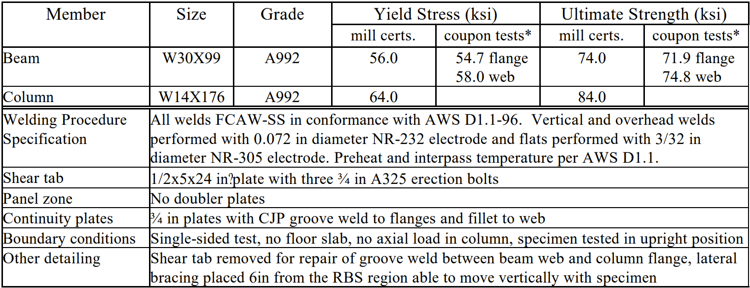
Four identical test specimens were subjected to different loading histories to investigate the effects of loading sequence and lateral bracing as a part of SAC project. Among them, the first test specimen, LS-1, was selected to be studied in this research since it has more available data in the literature. The connection details are shown in Figure 1.1.
Fig. 1.1: Connection details (Uang et al., 2000)
Sizes of the beam and column are W30X99 and W14X176, respectively, and both are made from ASTM A992 Steel. Web and flange of the beam are welded to column flange using a complete-joint-penetration (CJP) groove weld as specified in AISC 358. Welding procedure details and measured material properties are presented in Table 1.1. Continuity plate with a thickness of. 3/4 in. and a corner clip of 1.79 in. is made from ASTM A572 Grade 50. It is welded to the flange of column using CJP groove weld and to the web of column with 5/16 in. double fillet. Shear tab is used for erection purpose and removed before testing.
Table 1.1: Material and specimen details.
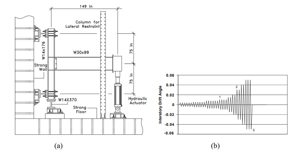
The standard SAC-multi-step loading history is applied at the end of the beam which is 149 in. away from the column centerline by hydraulic actuator. The column is laterally restrained and the top and bottom of the column are restricted to strong wall and floor. Test setup and applied loading history are presented in Figure 1.2.
Figure 1.2: (a) Test setup; and (b) loading history (Uang et al., 2000).
The main observations made during the test by the researchers are as follows:
- Significant yielding develops in the RBS region
- Moderate yielding occurred in the column panel zone
- Buckling of the beam was observed during the 3% drift cycles
- Test is stopped after three cycles at 5% drift
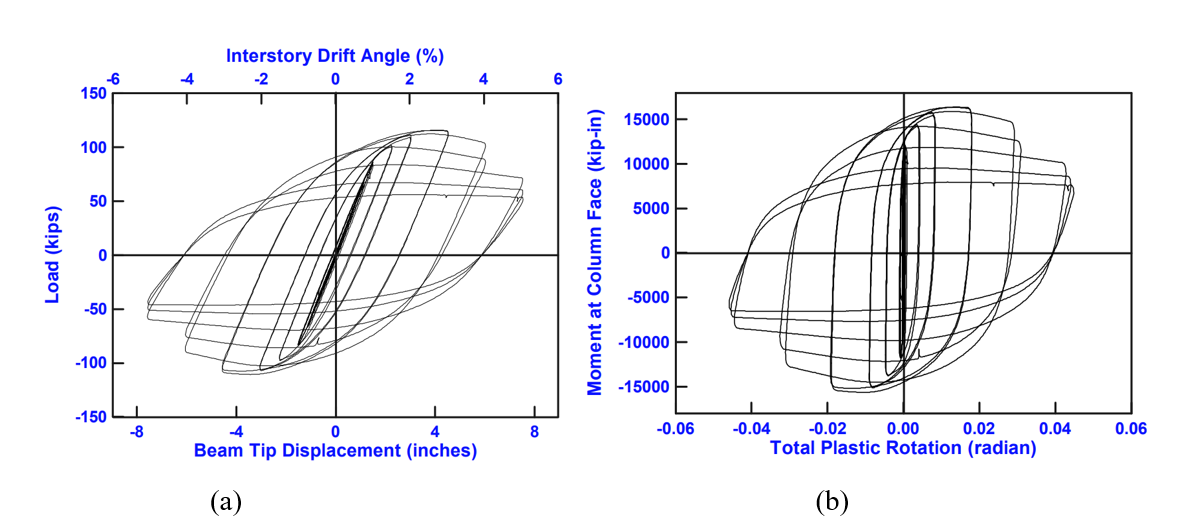
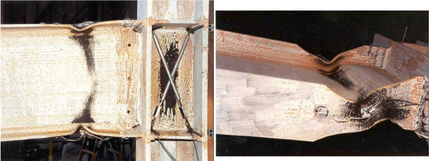
Actuator force-displacement and global moment-plastic rotation relations as well as photos after the peak of the third cycle of 5% drift are presented in Figures 1.3 and 1.4
Figure 1.3: (a) Actuator force-displacement; and (b) global moment-plastic rotation relations (Uang et al., 2000).
Figure 1.4: Specimen after testing (Uang et al., 2000).
1.3 Code Design Calculations
The following design checks outlined in AISC 358 were performed for the selected test specimen, and five additional variations were developed.
- Check the prequalification limits for column and beam (AISC 358 Section 5.3)
- Check RBS dimensions (AISC 358 Eq. 5.8-1-5.8-3)
- Check that prob. max. moment at the face of the column, Mf, does not exceed available strength fdMpe. (ANSI/AISC 358 Eq. 5.8-8)
- Check beam shear strength (AISC 360-16, Eq. J4-3)
- Check beam web-to-column connection (AISC 358 Eq. 5.8-9)
- Check the beam web-to-column connection. (AISC 358 Section 5.6)
- Check continuity plate requirements. (AISC 358 Chapter 2)
- Check column-beam relationship. (AISC 358 Section 5.4)
- Check shear strength of panel zone (AISC 358 Section 5.4)
- Check flexural strength at the centerline of the RBS (AISC Specification F2-1)
It is assumed that frame system satisfies the requirements of SMF. For the calculation of shear force at the center of RBS, VRBS, the distance between column centerlines, L, is assumed to be equal to 360 in. For design calculation of the test specimen, the material properties based on the mill test report were used for beam and column while material properties given in AISC Table Manual Table 2-5 were used for the continuity plate. For comparison purpose, it is intended to represent test condition with a tip load on the beam which is 149 in. away from the column centerline. The self-weight of the beam is neglected. It is assumed that the load combination 6 from ASCE/SEI 7 Section 12.4.2.3 is governing, and the required flexural and shear strength at the face of the column and the centerline of the RBS region are as follows:
- Vu@RBS = 40 kip (at the centerline of the RBS)
- Vu@FOC = 40 kip (at the face of the column)
- Mu@RBS = 4976 kips-in (at the centerline of the RBS)
- Mu@FOC = 5656 kips-in (at the face of the column)
AISC limitations were checked for the baseline test specimen (LS-1) and presented in Table 1.2 (for details, see Appendix A).
Table 1.2: AISC Design Checks for the baseline specimen (LS-1)
| AISC Design Checks | LS-1 |
| Prequalification limits for column and beam | OK |
| RBS dimensions | OK |
| Moment at the face of the column > Plastic moment of the beam | OK |
| Beam shear strength | OK |
| Beam web-to-column connection | OK |
| Continuity plate (double-sided fillet weld) | Not OK |
| Column-beam relationships | OK |
| Panel zone strength | OK |
| Flexural strength | OK |
It is observed that the amount of the weld between the continuity plate and column web (5/16 in. double-sided fillet) is less than the required amount of double-sided fillet weld of 1/2 in. according to AISC Manual Eq. 8-2a. Although this connection would not be allowed to be used in SMF system according to the updated AISC requirements, but it is seen from the test observation that it has no significant effect on the yielding first occurring on RBS cut of the beam. Flexural strength of the RBS cut of the beam is determined according to AISC 360 Eq. F2-1, AISC 358 Eq. 5.8-4 and using \(\phi_{d}\) of 1.0 (for ductile limit) specified in AISC 358 Section 2.4.1 as follows
Mn = Mp = Fy⋅Zx (AISC 360 Eq. F2-1)
ZRBS = Zx – 2⋅c⋅tf⋅(d-tf) (AISC 358 Eq. 5.8-4)
\(\phi_{d}\) = 1.0 (AISC 358 Section 2.4.1)
where
- Mn : the nominal flexural strength of beam
- Mp : plastic moment of beam
- Fy : specified minimum yield stress
- Zx: plastic section modulus of beam taken about X-axis
- ZRBS : plastic section modulus of center of reduced beam taken about X-axis
- d : depth of beam
- c : depth of cut at beam section
- tf : thickness of flange of beam
- \(\phi_{d}\) : Resistance factor for ductile limit
Nominal and available flexural strength at the center of RBS cut of the baseline specimen can be computed as follows:
Mn@RBS = Fy⋅ZRBS = (56 ksi)⋅(209.9in.3) = 11,754 kips-in.
\(\phi\)Mn@RBS = (1.0)⋅(11,754 kips-in.) = 11,754 kips-in.
Five additional variations were developed as presented in Table 1.3. For the first three variations, size of the column and beam elements were varied with respect to baseline model while the last two variations were varied with respect to variation 2. To be able to have a need of column-web doubler plate, it is assumed that there is another beam with the same size connected to column on the other side. The length of the column is equal to 400 in. while the length of the column centerlines are assumed to be equal to 400 in. and 300 in., respectively. Material properties of column and beam (ASTM A992) and continuity plate (ASTM A572 Grade 50) from AISC Manual Tables 2-4 and 2-5 are as follows:
ASTM A992
Fy = 50 ksi
Fu = 65 ksi
ASTM A572 Grade 50
Fy = 50 ksi
Fu = 65 ksi
The design checks were performed following the same procedure shown in Table 1.4. The calculated design capacities are presented in Table 1.5 (for details of Var-4, see Appendix B).
Table 1.3: Properties of variations
| Properties | LS-1 | LS-2 | LS-3 | LS-4 | LS-5 | LS-6 |
| Column | W14X176 | W14X176 | W14X176 | W18X192 | W12X170 | W12X136 |
| Thickness of doubler plate | - | - | - | - | 3/8 in. | 1/2 in. |
| Beam | W30X99 | W27X94 | W24X68 | W30X99 | W24X68 | W24X68 |
| Beam cut - a [in.] | 7 | 6 | 5 | 7 | 5 | 5 |
| Beam cut - b [in.] | 20 | 19 | 17 | 20 | 17 | 17 |
| Beam cut - c [in.] | 2.63 | 2 | 2 | 2.63 | 2 | 2 |
| Stiffener plate - thickness [in.] | 0.75 | 0.75 | 0.75 | 0.75 | 0.75 | 0.75 |
| Stiffener plate - depth [in.] | 7.5 | 7.5 | 7.5 | 7.5 | 7.5 | 7.5 |
| Stiffener plate - length [in.] | 9 | 9 | 9 | 9 | 9 | 9 |
| Stiffener plate - double-sided weld [in.] | 0.31 | 0.31 | 0.31 | 0.31 | 0.31 | 0.31 |
Table 1.4: Design checks for the variations
| AISC Design Checks | Var-1 | Var-2 | Var-3 | Var-4 | Var-5 | Var-6 |
| Prequalification limits for column and beam | OK | OK | OK | OK | OK | OK |
| RBS dimensions | OK | OK | OK | OK | OK | OK |
| Moment at the face of the column > Plastic moment of the beam | OK | OK | OK | OK | OK | OK |
| Beam shear strength | OK | OK | OK | OK | OK | OK |
| Beam web-to-column connection | OK | OK | OK | OK | OK | OK |
| Continuity plate (double-sided fillet weld) | Not OK | Not OK | Not OK | Not OK | Not OK | Not OK |
| Column-beam relationships | OK | OK | OK | OK | OK | OK |
| Panel zone strength | OK | OK | OK | OK | OK | OK |
| Flexural strength | OK | OK | OK | OK | OK | OK |
Table 1.5: Design capacities of the variations
| Variations | Column size | Beam size | Thickness of doubler plate | Available flexural design strength at centerline of the RBS cut of beam (kips-in.) |
| Var-1 | W14X176 | W27X94 | - | 9,978 |
| Var-2 | W14X176 | W24X76 | - | 6,146 |
| Var-3 | W18X192 | W30X99 | - | 11,750 |
| Var-4 | W12X170 | W24X76 | 3/8 in. | 6,146 |
| Var-5 | W12X136 | W30X99 | 1/2 in. | 6,146 |
1.4. IDEA StatiCa Analysis
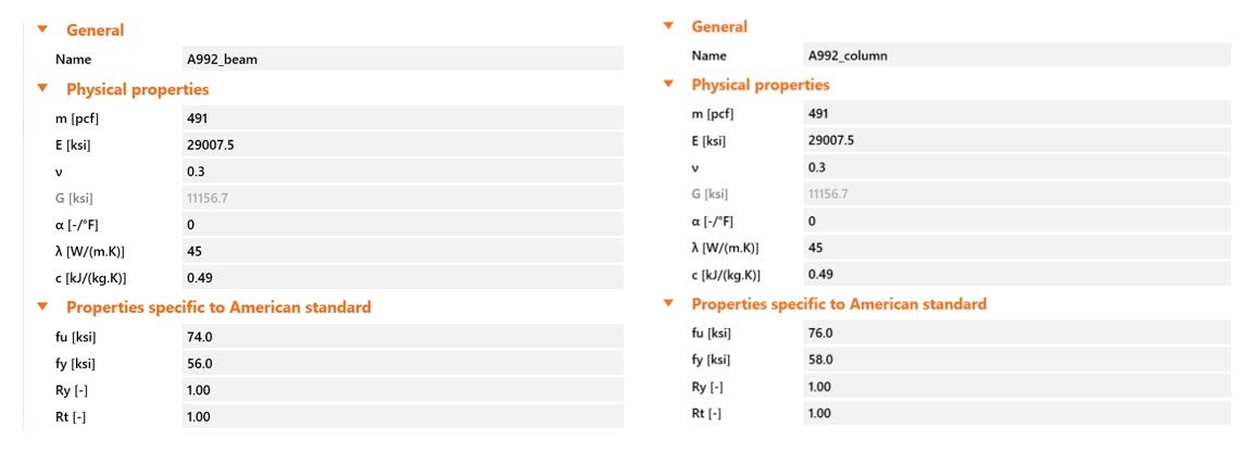
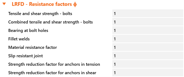
Two different analyzes were performed in IDEA StatiCa. The first one is to investigate the capacity of the baseline specimen under the test condition while the second one is to compute moment-rotation relationship of the connection. First, the test specimen was modeled in IDEA StatiCa. Then, material properties of mill certificate were introduced and overstrength coefficients, Ry and Rt, were set equal to 1.0 (see Figure 1.5). Also, all LRFD resistance factors were set to 1.0 as shown Figure 1.6.
Figure 1.5: Material properties of the test specimen in IDEA StatiCa; a) beam, b) column.
Figure 1.6: LRFD resistance factors in IDEA StatiCa.
1.4.1 Capacity analysis
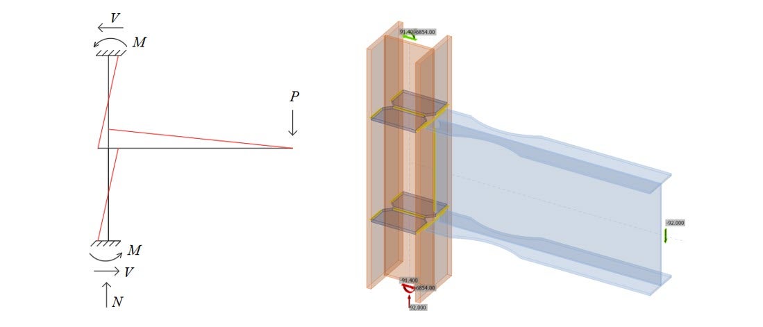
For the capacity calculation, “EPS” analysis type was chosen. Then, “Loads in equilibrium” option was selected to represent the test setup conditions under “Design”. In this selection, internal forces at each node of the frame should be introduced to the system. Default column length of IDEA StatiCa model is equal to 194.55 in. (2·(4+1.25)·bc+db). Since the current version of IDEA StatiCa does not allow to change the length of column, it is assumed that the column length of the IDEA model is equal to the length of test setup (150 in.). It is assumed that the column is fixed at both ends as presented in Figure 1.7(a), the loads to be applied to the model using “loads in equilibrium option” (Figure 1.7(b)) can be calculated as follows:
V = P·(149 in.)/150 in.
M = P·(149 in.)/2
N = P
where
- P: vertical load applied on the beam at the position of 149 in.
- V: shear applied at the column ends
- N: axial load applied at the bottom of the column
- M: moment applied at the column ends
Figure 1.7: (a) Loads in the frame system, and (b) Loads in IDEA StatiCa when P = 92 kips.
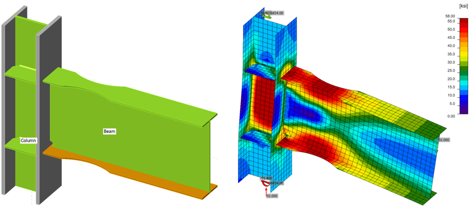
After incremental loading applied in IDEA StatiCa by updating all loads at each step, it was observed that yielding starts at RBS region of the bottom flange when vertical load, P, applied on the beam at 149 in. away from the column centerline reached 92 kips. The distance between the load application point and the center of RBS cut, LRBS, can be calculated by subtracting the half of the column depth and the distance between center of RBS cut and column face from the 149 in. as:
LRBS = 149 in. – (15.2 in./2) – 17 in. = 124.4 in.
The moment value at the center of RBS cut, MyRBS-IDEA, produced from the applied vertical load, P, can be calculated as:
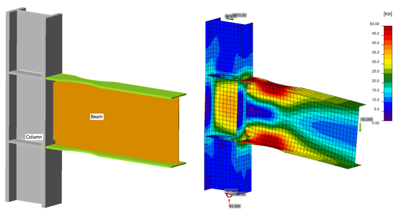
MyRBS-IDEA = P⋅LRBS = MyRBS-IDEA = (124.4 in.)⋅(92 kips) = 11,445 kips-in. (Figure 1.8)
Figure 1.8: IDEA StatiCa model for LS-1.
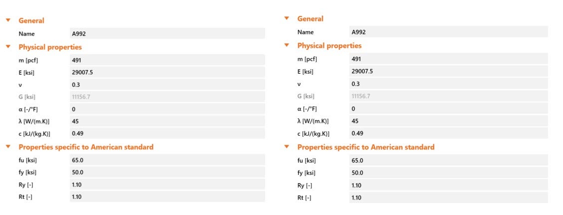
IDEA StatiCa models for the five additional variation connections (See Table 1.3) were developed using the AISC specified material properties given in AISC Manual Tables 2-4 and 2-5 shown in Figure 1.9.
Figure 1.9: Material properties for the variations in IDEA StatiCa; a) beam, b) column.
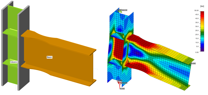
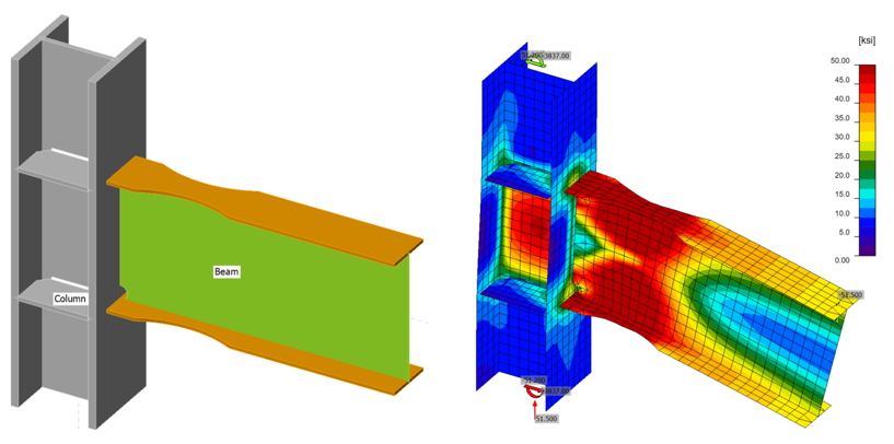
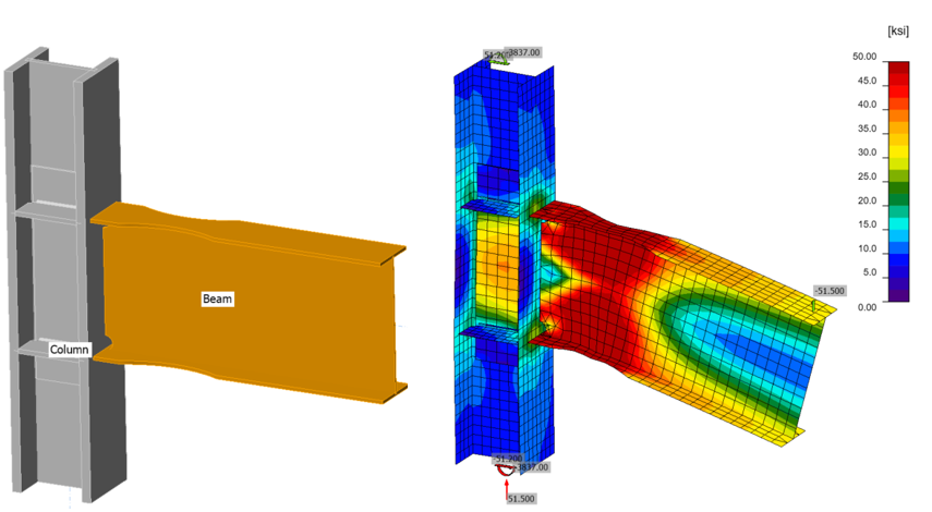
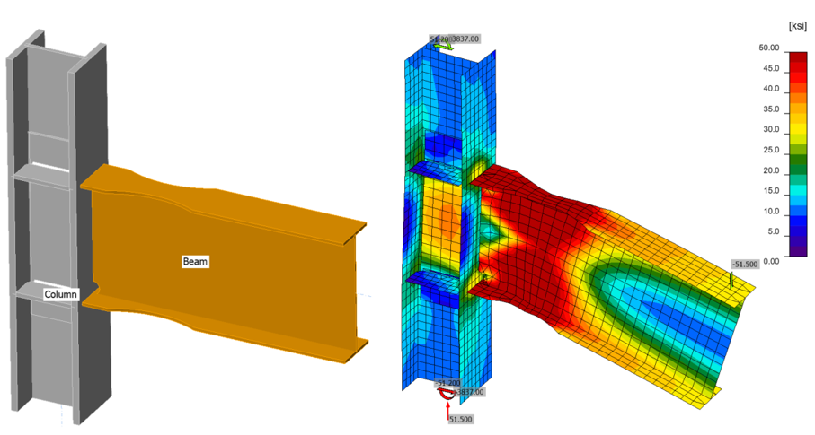
Following the same procedure, the capacities of five variation connections were computed using IDEA StatiCa shown in Table 1.6 and Figures 1.10-1.14.
Table 1.6: Design capacities of the variations
| Variations | Column size | Beam size | Thickness of doubler plate | Available flexural design strength at centerline of the RBS cut of beam (kips-in.) |
| Var-1 | W14X176 | W27X94 | - | 9,644 |
| Var-2 | W14X176 | W24X68 | - | 6,587 |
| Var-3 | W18X192 | W30X99 | - | 10,490 |
| Var-4 | W12X170 | W24X68 | 3/8 in. | 6,587 |
| Var-5 | W12X136 | W24X68 | 1/2 in. | 6,587 |
Figure 1.10: IDEA StatiCa model for variation 1.
Figure 1.11: IDEA StatiCa model for variation 2.
Figure 1.12: IDEA StatiCa model for variation 3.
Figure 1.13: IDEA StatiCa model for variation 4.
Figure 1.14: IDEA StatiCa model for variation 5.
1.4.2 Moment-rotation analysis
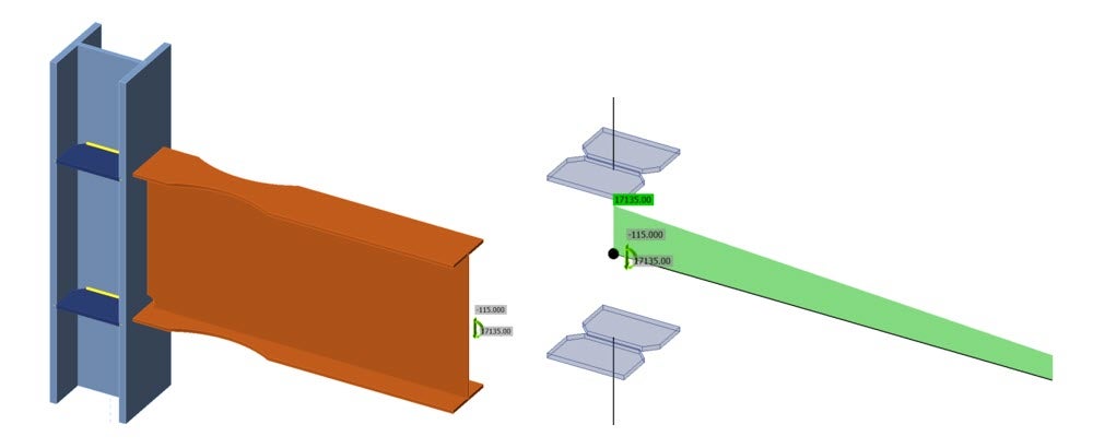
Moment-rotation analysis is computed with “ST” (abbreviation for stiffness) analysis type. The maximum vertical force applied during the experiment, 115 kips, was applied at the beam position of 0 (zero) in. in negative z direction (Vz = -115 kips), and the corresponding moment of 17,135 kips-in. (115 kips×149 in.) is applied around Y axis (My = 17,135 kips-in.) as presented in Figure 1.15.
Figure 1.15: IDEA StatiCa ST analysis: (a) solid view: (b) wireframe view.
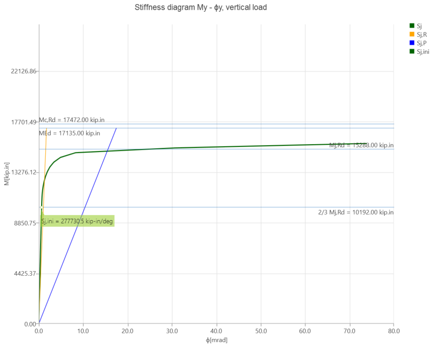
Under these loads, the moment-rotation graph excluding elastic rotation of beam and column was obtained as shown in Figure 1.16 where:
- Sj: moment-rotation curve shown with
- Sj,R: limit value – rigid joint
- Sj,P: limit value – nominally pinned joint
- Sj,ini: initial rotational stiffness
Figure 1.16: Moment-rotation relationship calculated by IDEA StatiCa.
1.5. ABAQUS Analysis
In this section, the results from IDEA StatiCa were compared to the ABAQUS software package (version 2021). ABAQUS is a robust general-purpose FEA code suitable for analyzing whole ranges of statics, dynamics, and nonlinear problems.
In this study, the IDEA StatiCa model developed in Section 1.4.2 for the moment-rotation analysis was chosen as a base model. The CAD model for the FEA analysis was generated using the IDEA StatiCa’s viewer platform. Numerical simulations with almost identical conditions (i.e., in terms of material properties, boundary conditions, and loading) were carried out using both IDEA StatiCa and ABAQUS.
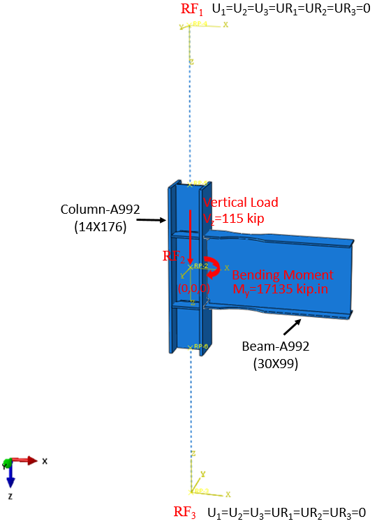
Figure 1.17: Model setup in ABAQUS.
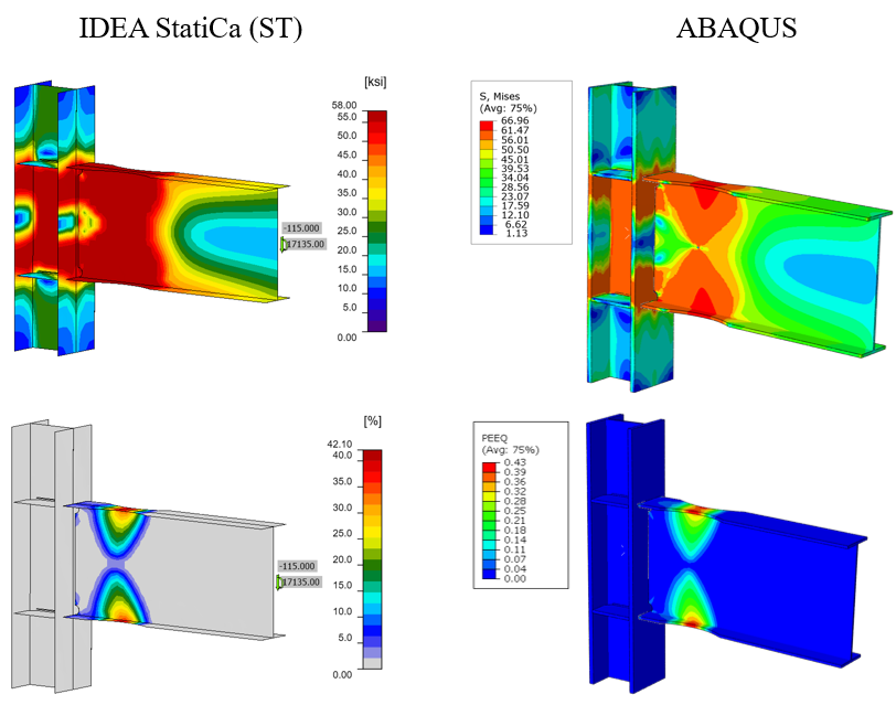
In ABAQUS, the element size and type were chosen to be 5 mm and C3D8R (3D stress, 8-node linear brick, reduced integration), respectively. In the ABAQUS model, the vertical load of 115 kips and the corresponding moment of 17,135 kips-in. (around Y axis) were applied to a defined reference point (i.e., RF2) as shown in Figure 1.17. The calculated length of the column in IDEA StatiCa is 194.55in as described in Section 1.4.1. Therefore, to mimic the identical column length in ABAQUS, two reference points (i.e., RF1 and RF3) were introduced 97.245 in. away from the center of the column along the Z axis in both directions. These two reference points were fixed in all directions and were connected to the top and bottom faces of the column using a connector builder module in ABAQUS. The tie constraint was applied between the weld lines and the attaching parts. The material behavior was modeled using bi-linear plasticity in ABAQUS. Other parameters, including density, elastic modulus, and Poisson’s ratio, were taken from the IDEA StatiCa materials library. The numerical simulation was carried out on four processors (Intel Xenon (R) CPU E5-2698 v4 @ 2.20GHz) and took approximately 45 minutes to finish. Figure 1.18 compares the predicted von-Mises stress and plastic strain between the IDEA StatiCa and ABAQUS models.
Figure 1.18: Comparison of the predicted von Mises stress (top row) and plastic strain (bottom row) between IDEA StatiCa and ABAQUS models.
The maximum predicted stress in IDEA StatiCa is 68 ksi (on top and bottom of the reduced section of the beam) while the ABAQUS model shows the maximum stress of 66.96 ksi at the same location. The slightly different stress distribution is likely due to the utilization of finer mesh in the ABAQUS model and the simplified CAD model in IDEA StatiCa. Also, the maximum predicted plastic strain in IDEA StatiCa and ABAQUS are 41.3% and 43%, respectively.
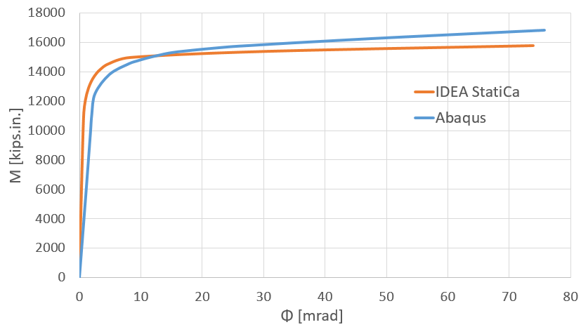
Figure 1.19 depicts the comparison of the moment-rotation curve between the two software.
Figure 1.19: Moment-rotation comparison between IDEA StatiCa and ABAQUS.
Note that in Figure 19, the blue curve (i.e., result from ABAQUS) represents the rotation of the beam which was measured at the intersection of the column and beam. Both models offer comparable initial stiffness estimations. The minor discrepancy could be associated with how that rotation is measured in each software, the difference in element types (i.e., solid element in ABAQUS versus shell element in IDEA StatiCa), and the employment of the tie constraint in ABAQUS to represent the welds.
1.6 Summary and Comparison of Results
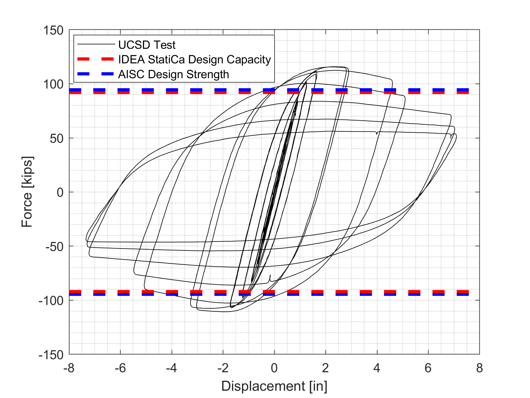
Tip load leading yielding at RBS cut calculated using IDEA StatiCa is 92 kips. The flexural design capacity of test specimen calculated following AISC code requirement was divided by the distance from the center of RBS cut to the actuator and the corresponding tip load was calculated as 94.5 kips (11,754 kips-in./124.4 in.). These two values are shown in the graph of force-displacement history presented in the test report, and the three sources (Test observation, AISC calculation and IDEA StatiCa) were compared in Figure 1.20. The capacity of the connection found by IDEA StatiCa is about 3% less than the one calculated based on AISC procedure. Although it is hard to say when yielding started from force-displacement history, it seems that both approaches capture yielding point very well.
Figure 1.20: Force-displacement relationship.
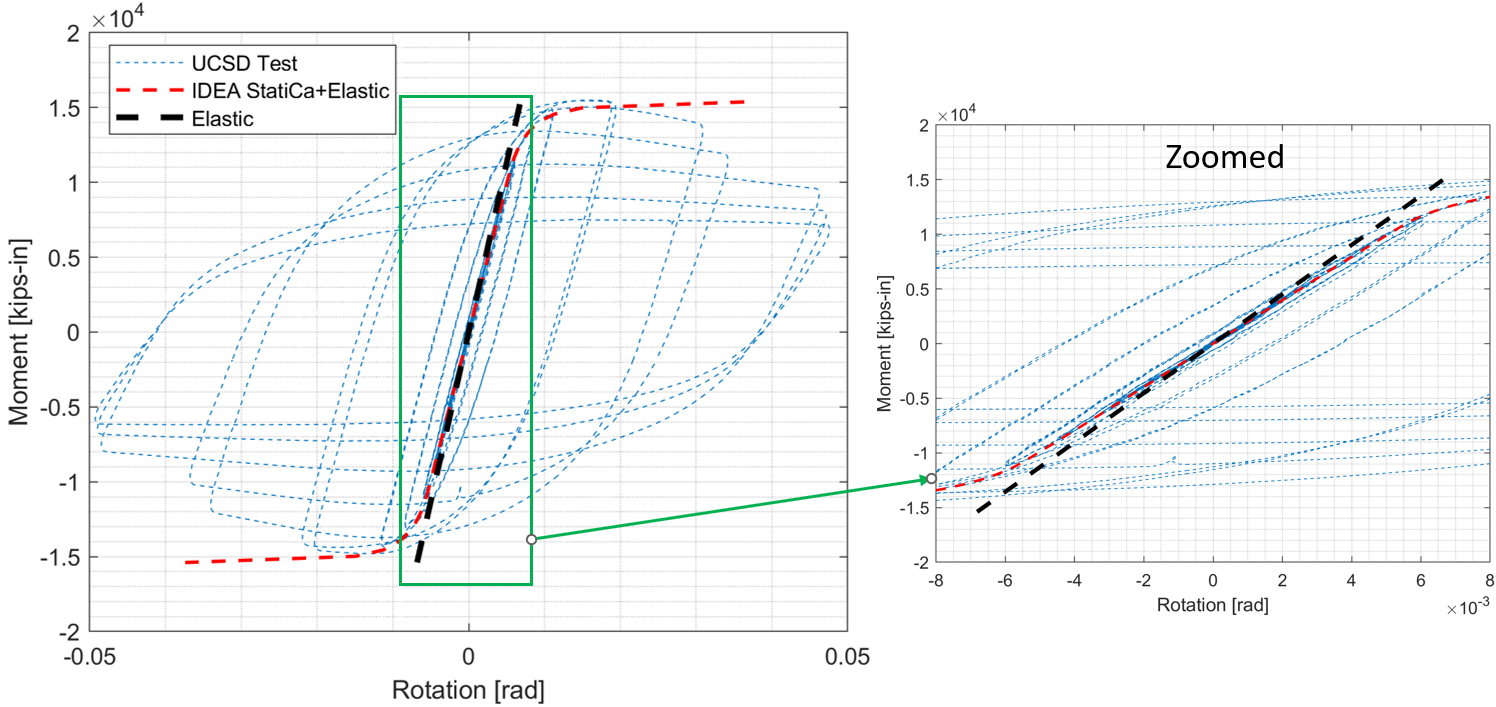
Moment-rotation relationship provided by IDEA StatiCa includes only plastic rotations. To be able compute plastic rotation, test researchers calculated elastic rotations for panel zone, beam and column analytically, and shared in the test output file. Using these data, elastic moment-rotation relationship was obtained, and added to the plastic moment-rotation curve of IDEA StatiCa to compare with the measured moment-rotation relationship as shown in Figure 1.21.
Figure 1.21: Moment-rotation comparison.
IDEA StatiCa shows very good initial stiffness and yielding estimation. The difference after yielding can be attributed to the bilinear material model used by IDEA StatiCa. It resulted in the strain-hardening of the steel material measured during the test is not captured by IDEA StatiCa.
Flexural capacity of the test specimen and five variations calculated using IDEA StatiCa and following AISC code requirement are presented in Table 1.7. The differences in the calculated capacities are less than 4%.
Table 1.7: Flexural capacity of the test specimen and five variations
| Specimen No | Column size | Beam size | Available flexural capacity of beam calculated using AISC procedure (kip-in.) | Available flexural capacity of beam calculated using IDEA StatiCa (kip-in.) |
| LS-1 | W14X176 | W30X99 | 11,754 | 11,445 |
| Var-1 | W14X176 | W27X94 | 9,644 | 9,454 |
| Var-2 | W14X176 | W24X68 | 6,587 | 6,407 |
| Var-3 | W18X192 | W30X99 | 10,490 | 10,076 |
| Var-4 | W12X170 | W24X68 | 6,587 | 6,407 |
| Var-5 | W12X136 | W24X68 | 6,587 | 6 |
In conclusion, based on the analyzes performed in this chapter, there was good agreement in capturing the yielding capacity of the RBS connection using IDEA StatiCa.
Read the full study on prequalified connections!
References
Uang, C., Yu, K., and Gilton, C. (2000) Cyclic Response of RBS Moment Connections: Loading Sequence and Lateral Bracing Effects, Report No. SSR-99/13, C. L. Powell Structural Research Laboratories, University of California at San Diego.
AISC (2016), “Specification for Structural Steel Buildings,” American Institute of Steel Construction ANSI/AISC 360-16, Chicago, Illinois.
AISC (2016), “Prequalified Connections for Special and Intermediate Steel Moment Frames for Seismic Applications, including Supplement No. 1,” American Institute of Steel Construction ANSI/AISC 358-16, Chicago, Illinois.
AISC (2016), “Seismic Provisions for Structural Steel Buildings,” American Institute of Steel Construction ANSI/AISC 341-16, Chicago, Illinois.
AISC (2020), “Seismic Design Manual,” 3rd edition, American Institute of Steel Construction, Chicago.
AISC (2017), “Steel Construction Manual,” 15th edition, American Institute of Steel Construction, Chicago, Illinois.
ABAQUS 2021, Dassault Systemes Simulia Corporation, Providence, RI, USA.
IDEA StatiCa s.r.o., Sumavska 519/35, Brno, 602 00 Czech Republic; https://www.ideastatica.com/support-center/general-theoretical-background


